FLEXIBLE LINERS INSTALLATION INSTRUCTIONS
The Installation Instructions on how to fit a flue liner are now available online. They are also available as a PDF download. Please click on the brochure cover to download the PDF, or browse this page for the relevant instructions.
Triplelock is a single wall stainless steel flexible flue liner designed for atmospheric gas and kerosene appliances where the flue gas temperature does not exceed 260°C.
TecnoFlex Plus is a twin skin flexible chimney liner designed for gas, oil and multi-fuel, where the maximum flue gas temperature does not exceed 600°C.
DESIGN GUIDE
Mandatory Requirements
Building Regulations Document J requires that a flexible flue liner can only be installed completely enclosed inside a masonry chimney. A non masonry enclosure such as timber or plasterboard boxing in is not acceptable.
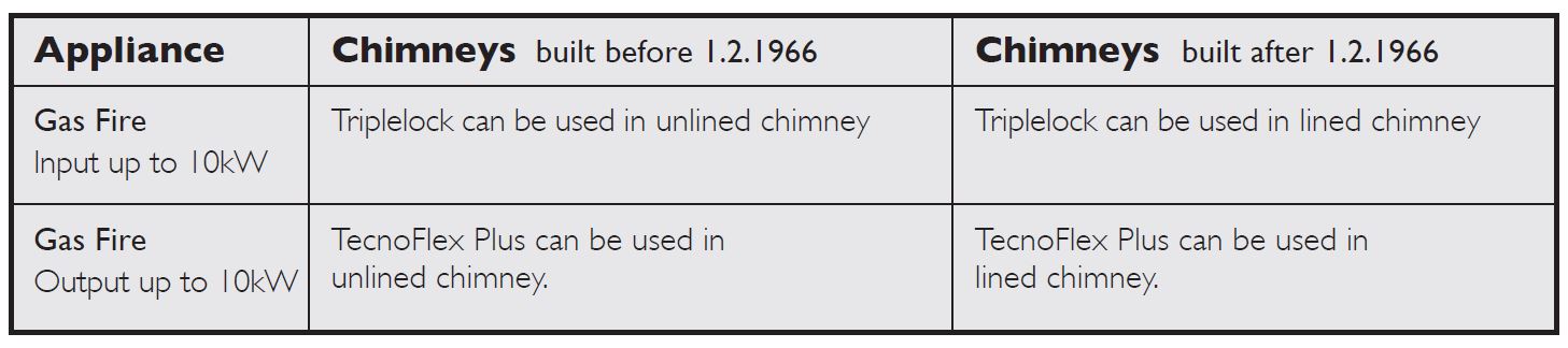
The type of flue liner permitted depends on the fuel to be used, the type of appliance and the type and year of chimney construction in which it is to be fitted.
Building Regulations Document J, outlines different requirements for relining masonry chimneys built before and after 1st February 1966.This is summarised in the table below.
| Appliance | Chimneys built before 1.2.1966 | Chimneys built after 1.2.1966 |
| Gas Burning Output up to 45kW |
Triplelock can be used in unlined chimney on dry applications. | Triplelock can be used in lined chimney on dry applications. |
| Kerosene Burning Output up to 45kW |
Triplelock can be used in unlined chimney on dry applications. | Triplelock can be used in lined chimney on dry applications. |
| Gas/Oil Burning Output up to 45kW |
TecnoFlex Plus can be used in unlined chimney on wet and dry applications. | TecnoFlex Plus can be used in lined chimney on wet and dry applications. |
| Solid Fuel Burning Output up to 45kW |
TecnoFlex Plus can be used in unlined chimney. | TecnoFlex Plus can be used in lined chimney. |
Connection to an appliance which is not connected to the fuel supply, should be carried out by a competent person.
We recommend the use of HETAS approved installers for solid fuel applications. If installation is carried out by a non HETAS registered installer, the installation must be certified by a local Building Control inspector. Connection to an appliance that is connected to the fuel supply must be carried out by a Gas Safe (Gas) or OFTEC (Oil) registered installer.
The design guide must be read in conjunction with the detailed component installation instructions. For full design and installation details the key referral documents are:
- BS EN 1856-2 Connecting Flue Pipes
- BS EN 1856-2: Flue Liners
- BS EN 1859: Metal Chimneys -Testing Methods
- BS EN 1443: Chimneys – General Requirements
- BS EN 15287-1: Chimneys. Design, installation and commissioning of chimneys. Chimneys for non-room sealed heating appliances.
- Approved Document J: – Combustion appliances and fuel storage systems (England & Wales)
- DFP Technical Booklet L Combustion appliances and fuel storage systems (NI)
- Technical Handbook (Domestic & Non Domestic),Section 3- Environment (Scotland)
- Appliance Installation Instructions and related standards. Other standards covering specific applications will also be relevant and must be adhered to.
Ensure all chimney components are available and check them to ensure there has been no damage. Do not use damaged components.
PRIOR TO INSTALLATION
Prior to Installation
In all cases the chimney should be inspected for deterioration and if necessary any remedial work required should be carried out. The chimney should be swept by a suitably qualified chimney sweep who would provide a certificate after sweeping and checking, which should be retained for future reference. A list of HETAS registered sweeps can be found at www.hetas.co.uk
It will be necessary to check that the flaunching at the top of the stack is not cracked, and if so replaced. The brickwork pointing and the flashings should be checked to ensure they are in good order and corrected as necessary. This is required to prevent ingress of rainwater, which, if mixed with carbon deposits on the inside wall of the chimney, could then damage the fabric of the building and the chimney liner.
Use of Flex Tester Kit
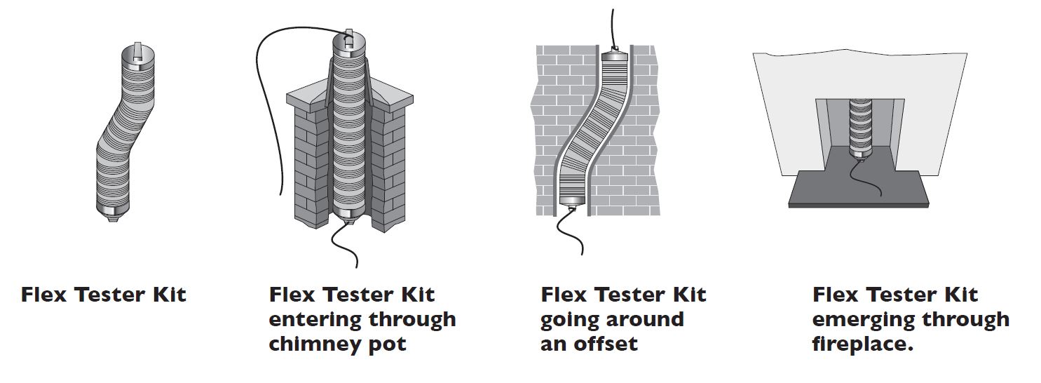
Prior to installation of the Flex, we recommend that a test length of approx., 1.5m with a nose cone attached to each end, is pulled through the chimney to ensure that the chimney is suitably sized and free from obstructions. Failure to do so may lead to the warranty being invalidated on the Flex if damage has been caused due to snagging on an obstruction.
The tester kit should be pulled down the chimney using a nose cone and string/rope. A re-usable 1.5m test length complete with two nose cones is available in the TecnoFlex Plus range. Alternatively nose cones can be purchased separately or as part of a Flex Installation kit.
Ventilation
It is very important that sufficient air for combustion is provided to the room containing the appliance, to enable correct and efficient working of the system. Reference should be made to the appliance manufacturer’s instructions and recommendations are also given in the Building Regulations Document J.
Carbon Monoxide Alarms
The carbon monoxide alarms should comply with BS EN 50291:2001.
Where a new or replacement fixed solid fuel appliance is installed in a dwelling, a carbon monoxide alarm must be provided in the room where the appliance is located.
Please follow manufacturers instructions with regards to siting and fixing or alternatively :-
a) On the ceiling at least 300mm from any wall or if it is located on a wall, as high up as possible (above any doors and windows), but not within 150mm of the ceiling and
b) between 1m and 3m horizontally from the appliance.
N.B
Provision of a carbon monoxide alarm should not be regarded as a substitute for correct installation and regular servicing.
Delivery to Site and Storage
Components should be carefully transported and off loaded. They should be inspected to ensure they have not been damaged, and should be stored off the ground and under cover so that they are protected from accidental damage and the adverse effects of weather.
CONNECTING FLUE PIPE
Connection to the Appliance or Flue Box
The connection to the appliance should be made using fire cement/rope or high temperature sealant to ensure a positive seal. Where TecnoFlex Plus is to be fitted to the top of an open fire place, a Schiedel Rite-Vent gather unit should be fitted into the throat of the chimney connected to the TecnoFlex Plus and sealed off.
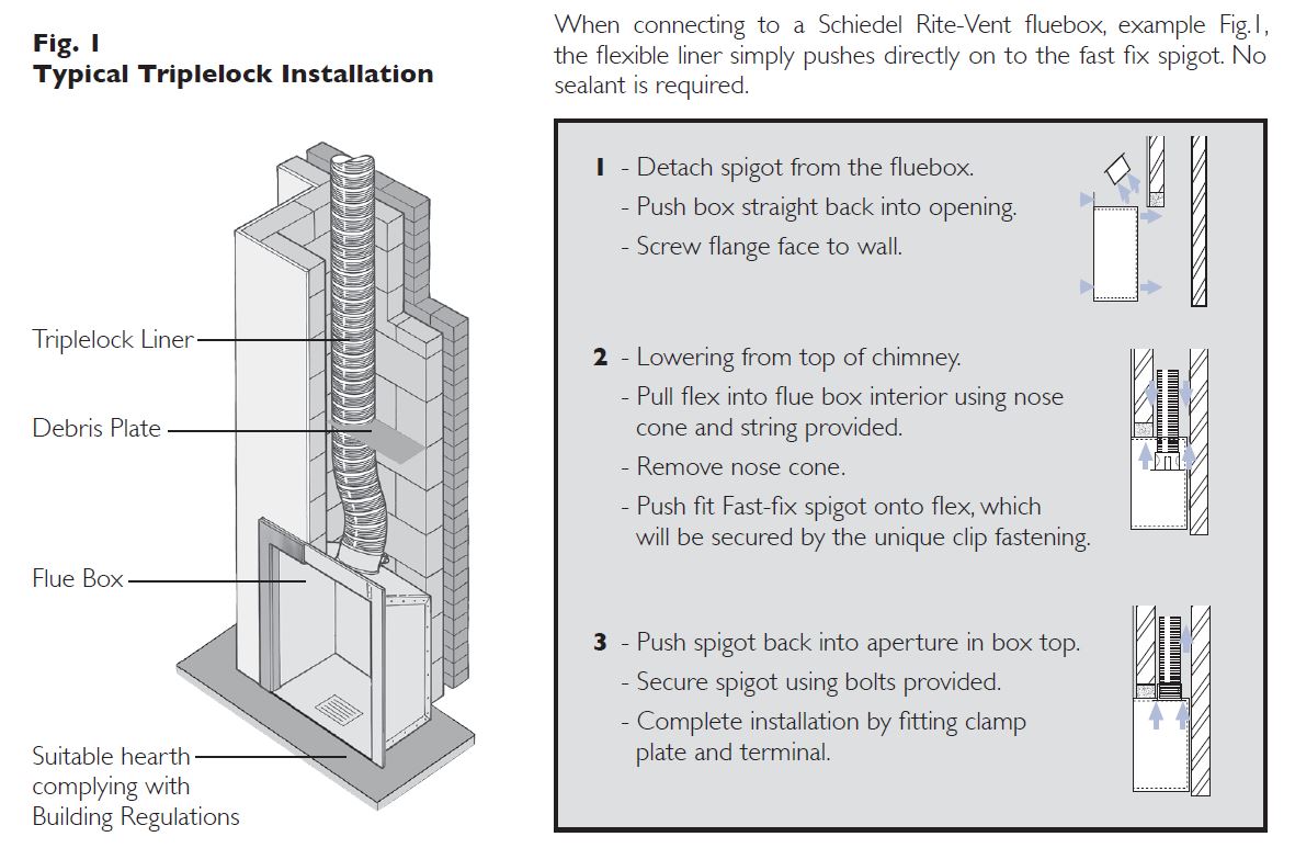
When connecting Triplelock flex to a Schiedel Rite-Vent flue box, the flexible liner simply pushes directly on to the fast fix spigot. No sealant is required.
When making a connection to a fluepipe in another product type, such as rigid stainless steel single or double wall or vitreous enamel, then the appropriate Schiedel approved connector to/from flexible should be used. The connector should be suitably sealed to the appliance spigot ensuring a gas tight joint.
Connecting Flue Pipe Diameter
Connecting Flue Pipe Diameter size should be as recommended by the appliance manufacturer. Under all circumstances the operational requirements of the appliance and the configuration of the flue must satisfy the flue sizing requirements of EN13384-1.
Distance to Combustibles
In accordance with building regulations, it is essential that the correct distance to combustible material is maintained on connecting flue pipes. On solid fuel applications, where there is a risk of soot fire, on unmeasured (NM) designated single wall product, this distance is 3 x ØInt of the pipe, e.g. for Ø125mm the distance is 375mm and
for Ø150mm the distance is 450mm to combustibles on both painted and non painted variants. On measured (M) single wall or double wall products this distance will be as declared by the chimney manufacturer.
Connecting Flue Pipe Route
Connecting flue pipes should only be used to connect appliances to a Chimney.They should not pass through any roof space, partition, internal wall or floor, except to pass directly into a chimney through either a wall of the chimney or a floor supporting the chimney.
Connecting flue pipes should be located as to avoid igniting combustible material.
On solid fuel appliances the maximum length of a connecting flue pipe is 2m.This distance is reduced to 1.5m if any of the acceptable alternative methods of connection are adopted as per BS EN15287-1. (See p.6 for full details.)
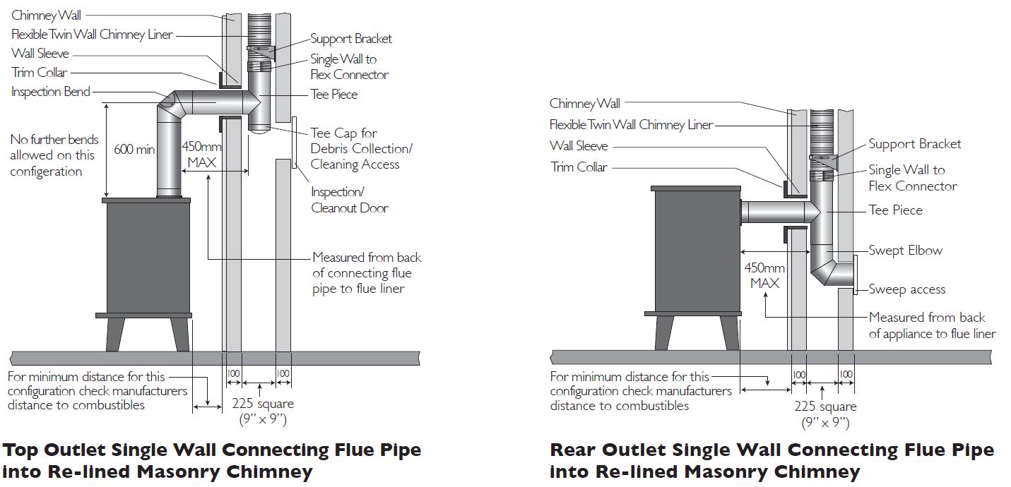
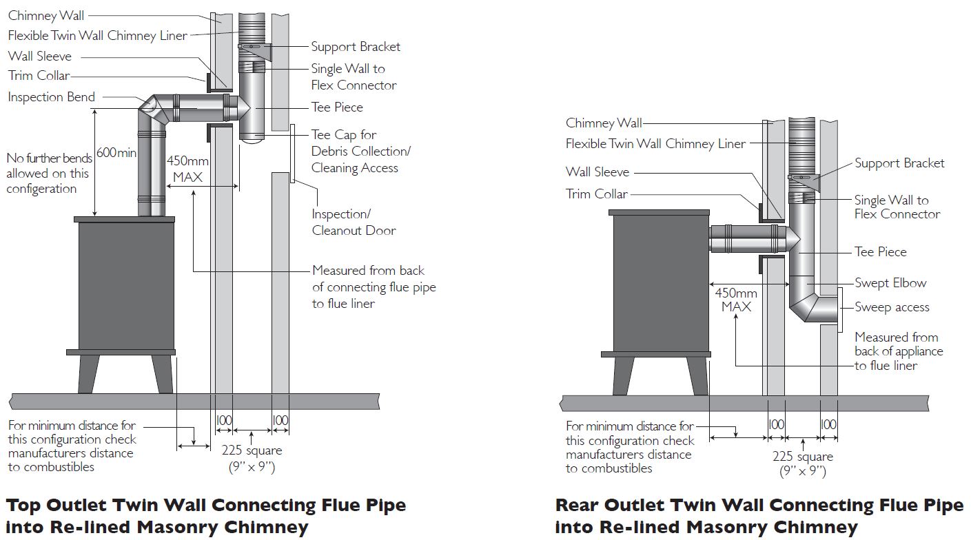
On appliances with a top outlet, it is recommended that a vertical run of at least 600mm should be allowed immediately above the appliance prior to any change of direction.
On appliances with a rear outlet, it is recommended that there is maximum of 150mm in the horizontal run however under certain conditions, as described in alternative methods in BS EN 15287-1, this may be increased to 450mm.
Within a system (Chimney + Connecting Flue Pipe) there should be no more than 4 changes of direction of maximum 45˚. 90˚ Factory made bends or tees within the system may be treated as being equal to two 45˚ bends (as per Document J of the Building Regulations issued October 2010).
Inspection
On solid fuel applications to conform to Building Regulations, provisions should be made to enable a chimney to be inspected and cleaned.
An inspection pipe, inspection elbow or a 90° or 135° Tee with tee cap can form a suitable inspection point (unless cleaning/inspection can be done through the appliance). To aid cleaning, sufficient distance should be left between changes of direction to permit the safe passage of cleaning brushes within the system. This is particularly important on solid fuel applications. It is recommended that chimneys serving solid fuel appliances be swept as frequently as necessary, but at least twice a year.
BS EN 15287-1
Acceptable Alternative Methods of Connection
Where a horizontal connecting flue of more than 150mm is required to connect a solid fuel fired appliance to a chimney, an installation method as per the examples below may be used provided the following criteria is met:-
- The maximum length of horizontal connecting flue pipe does not exceed 450mm;
- A Defra exempt appliance or an appliance, which is limited to burning authorised smokeless fuel only, is installed;
- A calculation according to BS EN 13384-1 has indicated safe operation of the proposed configuration, and the results of the calculation are left with the householder along with the appliance installation instructions
- The appliance manufacturer agrees in writing to the proposed configuration;
- The chimney manufacturer agrees in writing to the proposed configuration;
- The total length of single wall connecting flue pipe is not more than 1.5m;
- The appropriate distances to combustible materials from both the appliance and the connecting flue pipe are maintained.
NOTE:
These alternative methods do not apply to Republic of Ireland.
 INSTALLATION OF THE LINER
Handling
Suitable PPE (Personal Protection Equipment) must be used when handling stainless steel flexible liners and accessories. PPE advised: Strong industrial gloves plus long sleeved overalls.
Liner Orientation
It is essential in the case of TecnoFlex Plus that the liner is installed the right way up. The arrow on the outside of the liner indicates the direction of flue gas flow and must be pointing upwards towards termination.Triplelock Flex can be installed either way up.
Cutting the Liner to the Correct Length for the Chimney
After the length of flue liner has been connected to the appliance, allow a sufficient length of liner to protrude above the clamp plate to secure the terminal and then cut, using suitable cutting equipment. At all times extreme care must be taken when cutting the liner and strong industrial gloves plus long sleeved overalls should be worn as cut edges are very sharp. In addition, any tape secured to the ends of the
liner, which is provided for safe handling prior to installation, must be removed before completion and commissioning of the full system.
|
Minimum Bending Radius |
|||||||||
|
Product |
80 |
100 |
125 |
155 |
180 |
200 |
230 |
250 |
300 |
|
Triplelock |
– |
250 |
315 |
390 |
450 |
500 |
575 |
625 |
750 |
|
TecnoFlex Plus |
240 |
300 |
375 |
465 |
540 |
600 |
690 |
750 |
900 |
Bending of the Liner
Great care should be taken to avoid overbending or kinking the liner on installation. The minimum bending radii are shown in the table alongside.
Support Components
All support components have been tested and approved for the mechanical performance declared by Schiedel Chimney Systems Ltd.
Triplelock, which is used exclusively on gas and oil applications, is relatively light and can be supported at the top of the chimney using a clamp plate fixed to the top of the masonry stack.
TecnoFlex Plus, however, is heavier and must be supported at both top and bottom of the stack. At the top of the stack there are two alternatives:
1. Plate and clamp fixed directly to the existing masonry stack
2. Pot Hanger/ Combined Pot Hanger & Terminal supporting the weight of the flex using the existing chimney pot. At the base of the stack a bottom support bracket should be used.
Ventilation
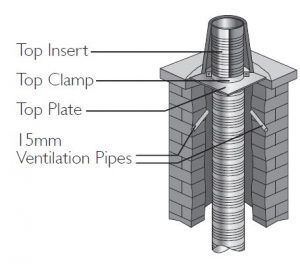
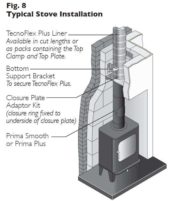
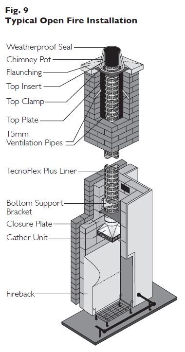
Where TecnoFlex Plus is used serving a solid fuel appliance,ventilation between the liner and the inside of the chimney will be required. This is provided by installing two 15mm pipes into the masonry at the top of the stack just below the top plate and clamp, at an angle to prevent the ingress of rainwater. lt would also be necessary to install a vent at the base of the stack above the debris plate or the gather unit.This should be an air brick or vent of 20cm (see Fig. 8, 9 ,10 p.10). If the cavity is to be insulated with pearlite, or tube wrap insulation, then two 15mm pipes at the top of the stack to allow any moisture in the insulation to evaporate freely, must still be provided.
Insulation
Where the chimney is highly exposed or in a large void, then insulation should be considered. If insulation is required, granules such as Vermiculite, should be poured in around the liner from the top of the stack after fitting a suitable closure plate at the bottom of the system. Alternatively a solid tube of high quality insulation can be used.
Under all circumstances, the chimney stack must be fully weather proofed prior to the installation of the liner and any insulation material. Failure to do so will render the warranty null and void.
Sealing the Flue Liner to the Chimney Pot
The plate and clamp holding the liner to the chimney top should be secured to the stack. To weather the top of the chimney stack, seal any gaps between the liner installation and the chimney pot using appropriate acid resistant mortar.
TECNOFLEX PLUS ACCESSORIES
Top of the Chimney
 Combined Pot Hanger & Terminal
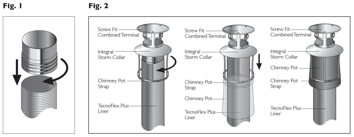
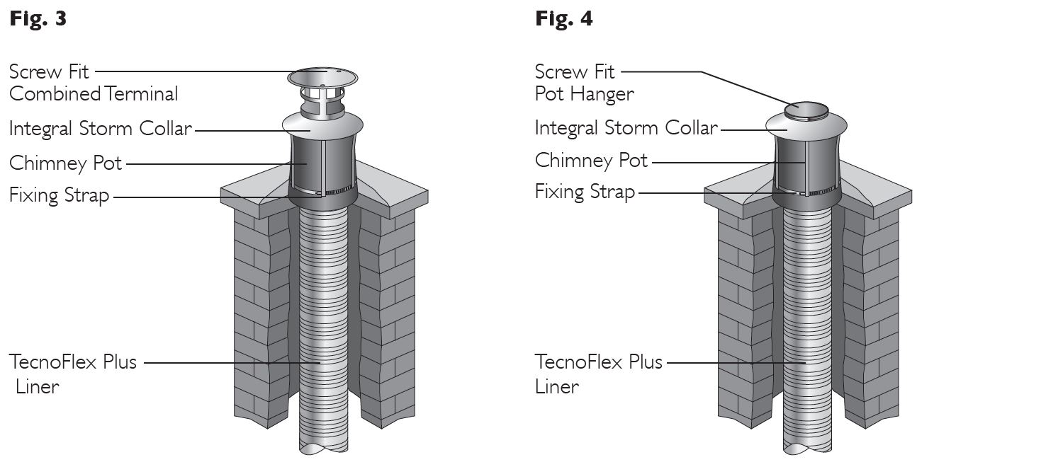
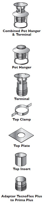 Combined Pot Hanger & Terminal supports the weight of up to 15m of TecnoFlex Plus using the existing chimney pot as an anchor point.The flex is pulled down the existing chimney stack using the nose cone (see p.13). Once the flex is in position at the base of the stack, with the single wall to flex adaptor fitted in place through the closure plate, at the top of the chimney, the flex protruding through the chimney pot should be cut off level with the top of the pot.The threaded adaptor on the bottom of the terminal is then screwed onto the outside of the TecnoFlex Plus liner (see Fig.1) until the storm collar rests on the top of the chimney pot.The three straps which are welded to the underside of the collar, are located to the outside of the pot (see Fig.2 opposite).The fixing strap in the kit is then fastened over these three straps, leaving approximately 50mm protruding below.The fixing strap is tightened into place using a screwdriver. The protruding ends on the three straps are then bent upwards into a loop around the fixing strap (see Fig.3).
Pot Hanger
The pot hanger is installed in the same way as the combined pot hanger and terminal (See Fig.1,2 & 4 opposite).
Terminal
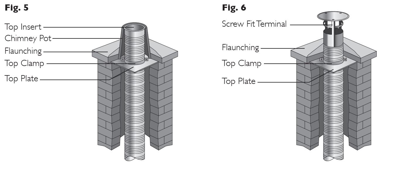
The screw fit terminal is used in combination with the plate and clamp (see Fig.6 opposite).The adaptor on the bottom of the terminal is screwed on to the flex (see Fig.1). Cement flaunching is then used up to and around the base of the terminal to make the system weather tight.
Top Clamp
The top clamp is used in combination with the top plate to support the weight of the liner at the top of the stack. The split band passes around the TecnoFlex Plus liner and is then tightened in place using the nuts and bolts provided. The band then rests on top of the top plate (see Fig.5 opposite).The top clamp will support the weight of up to 20m of TecnoFlex Plus.
Top Plate
The top plate is used in combination with the top clamp to support the weight of the liner at the top of the stack. (see Fig.5 opposite)The top plate should be fixed securely in place and flaunched to make weather proof
Top Insert
A top insert should be used to protect the top of the flex inside the chimney pot (see Fig.5 opposite). The area between the flex and the chimney pot should be sealed to prevent water ingress.
Adaptor TecnoFlex Plus to Prima Plus
The adaptor from TecnoFlex Plus can be used as an alternative to the top insert, or to connect from product within the chimney stack. It is secured to the flex as shown in Fig.1 opposite.The area between the adaptor and the chimney pot should be sealed to prevent water ingress.
CE APPROVED ADAPTOR RANGE
Connection from the Appliance
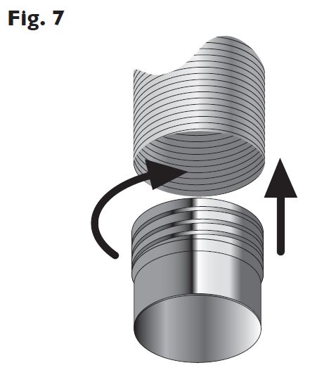
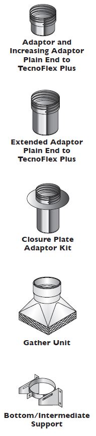 Adaptor and Increasing Adaptor Plain End to TecnoFlex Plus *
The adaptor is attached to the TecnoFlex Plus (see Fig. 7 opposite) by screwing the adaptor in a clockwise direction until the edge of the TecnoFlex Plus is located between the liner and the threaded outer wall of this component. On high temperature applications, no sealant is required on the screwfit joint. The plain end of the adaptor protrudes through the hole in the closure plate at the base of the chimney stack.The protruding end of the adaptor then fits inside the vitreous enamel or stainless steel stove pipe. This joint between the plain spigot and the stove pipe should be sealed with fire cement/rope or appropriate high temperature sealant.
Extended Adaptor Plain End to TecnoFlex Plus
Installed as per adaptor Plain End to TecnoFlex Plus.
* Closure Plate Adaptor Kit
Available in two styles: One and two piece.
The two piece consists of two parts, a ring and an extended plain end to TecnoFlex Plus adaptor, this adaptor is fitted as per the adaptor plain end to TecnoFlex Plus. The ring is then slid up around the spigot and fastened to the underside of the closure plate to provide a neat aesthetic finish on site (see Fig. 8 opposite).
The one piece consists of a plain end to Tecnoflex Plus adaptor and a fixed ring, this adaptor is fitted as per the adaptor plain end to TecnoFlex Plus, fastened to the underside of the closure plate to provide a neat aesthetic finish on site.
Gather Unit
The TecnoFlex Plus is fastened inside the socket protruding from the top of the gather unit and the joint sealed using fire cement/rope or appropriate high temperature sealant.The gather should then be fixed to the inside of the masonry chimney to create a seal with the chimney wall (See Fig. 9 opposite).
Bottom/Intermediate Support
The support bracket is used to fasten the liner to the wall of the masonry chimney, to prevent lateral movement during sweeping of the chimney (See Fig. 8, 9 & 10 opposite).
CE APPROVED ADAPTOR RANGE
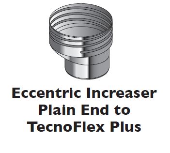 Eccentric Increaser Plain End to TecnoFlex Plus
Installed as per Adaptor Plain end to TecnoFlex Plus on p.9
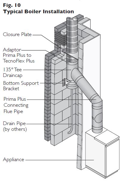
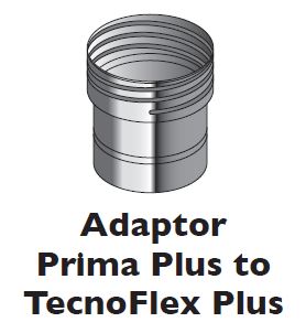 Adaptor Prima Plus to TecnoFlex Plus
Attached to the TecnoFlex Plus and fitted through the closure plate as per the adaptors above, the male spigot is pushed inside the female socket of the Prima Plus connecting flue pipe and the joint secured using a locking band. On high temperature applications, no sealant is required between the flex and the adaptor, however on condensing applications, an acid resistant sealant, such as Rotempo, or equivalent, is required to seal this joint. Please contact Schiedel Chimney Systems for details.
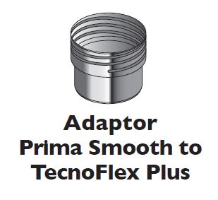 Adaptor Prima Smooth to TecnoFlex Plus
Fitted as per the Prima Plus to TecnoFlex Plus adaptor, however no locking band is required between the spigot of the adaptor and the Prima Smooth connecting flue pipe. No sealant is required between the screwfit part of the adaptor and the TecnoFlex Plus on high temperature applications.
N.B. Prima Smooth is used only on High Temperature applications. For condensing applications Prima Plus must be used.
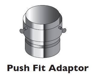 Push Fit Adaptor
The TecnoFlex Plus is pushed down between the two walls of the adaptor. The screws are then tightened to fasten the flex securely in place. The joint is then sealed using fire cement or an appropriate high temperature sealant
Nosecone
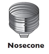 The nosecone is fastened to the TecnoFlex Plus by twisting in a clockwise direction. A length of rope or string is attached to the handle on the nose cone, which is then used to pull the TecnoFlex Plus down the chimney. The component is then unfastened and may be used on subsequent installations.
Screw Fit Joiner
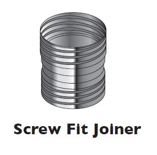 Joiners are only permitted if the chimney liner length exceeds the maximum length of flex available and details of the installation have been approved in advance, in writing, in compliance with product warranties. The joiner is screwed onto the TecnoFlex Plus liner as per a standard adaptor.
TRIPLELOCK ACCESSORIES
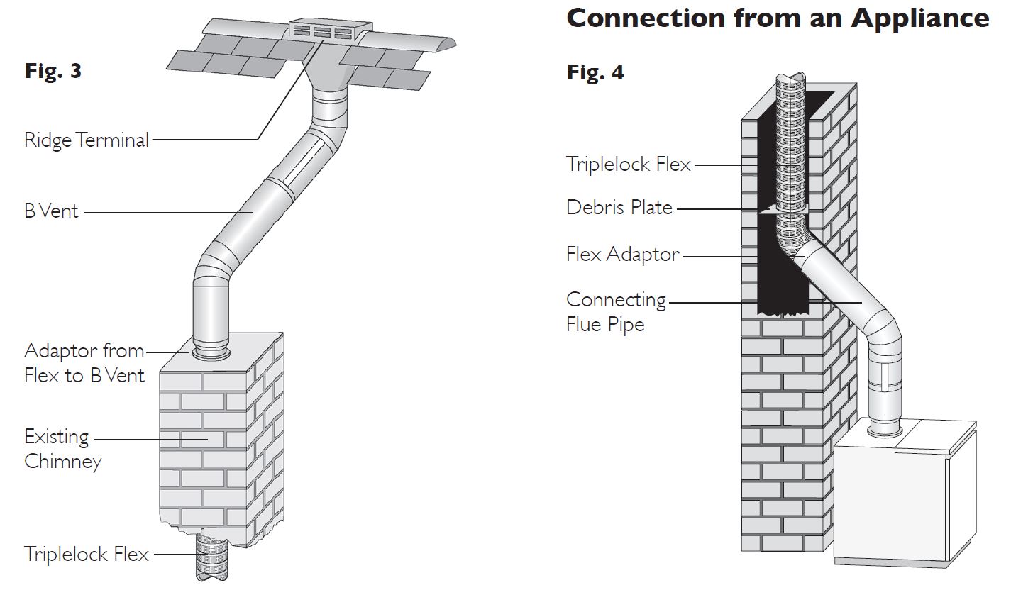
When making a connection to a flue pipe in another product type, such as B Vent, rigid stainless steel single or double wall or vitreous enamel, then the appropriate connector to/from flexible should be used (see Fig. 3). The joint should be suitably sealed to ensure a gas tight joint.
 FGC Economy Terminal
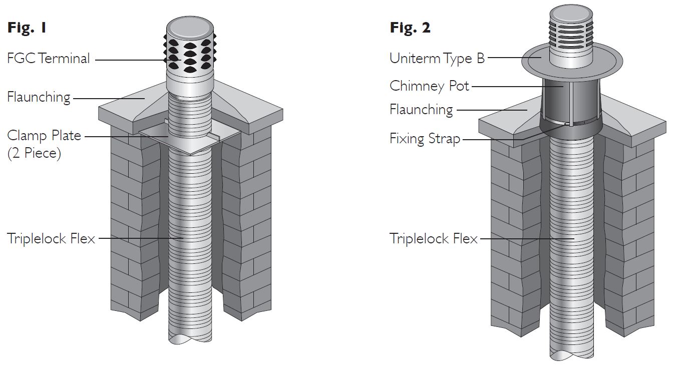
75mm of flex is required to ensure a positive location of the flex within the terminal. Once the flex is fixed in position, the FGC Terminal is pushed down over the top of the flex, with the inward bead on the terminal acting as a location and stop point for the flex. Cement flaunching is then used up to and around the base of the terminal to make the system weather tight (see Fig. 1).
Cast Aluminium Terminal
75mm of flex is required to ensure a positive location of the flex within the terminal. Once the flex is fixed in position, the terminal is pushed down over the top of the flex, with the ridge on the inside of the terminal acting as a location and stop point for the flex. Cement flaunching is then used up to and around the base of the terminal to make the system weather tight.
Uniterm Type B
The Uniterm Type B supports the weight of the flex using the existing chimney pot as an anchor point. The base of the Uniterm is lowered over the top of the flex, ensuring that the flex does not protrude beyond the stop bead in the terminal. 3 self tapping screws are provided to fasten the Uniterm securely to the flex. The liner is then lowered down the chimney until the storm collar rests on the top of the chimney pot.The three straps (see Fig. 2) which are attached to the underside of the storm collar, are located to the outside of the pot.The fixing strap in the kit is then fastened over these three straps, leaving approximately 50mm protruding below. The fixing strap is tightened into place using a screwdriver. The protruding ends on the three straps are then bent upwards into a loop around the fixing strap.
Universal Terminal
75mm of flex is required to ensure a positive location of the flex within the terminal. Once the flex is fixed in position, the Universal Terminal is pushed down over the top of the flex, with the bead on the inside of the terminal acting as a location and stop point for the flex. Cement flaunching is then used up to and around the base of the terminal to make the system weather tight.
Clamp Plate (2 Piece)
The clamp plate is used to support the weight of up to 15m of the liner at the top of the stack.The two piece plate passes around the liner and is then tightened in place using the nuts and bolts provided.The top plate should be fixed securely in place and then flaunched to make weather proof.
Clamp & Plate
The clamp and plate are used to support the weight of up to 15m of the liner at the top of the stack. The flex protrudes through the top plate and the two- piece split band is then fastened tightly around the flex using the nuts and bolts provided. Sufficient flex should be left protruding through the clamp plate to allow for positive location within the terminal.The top plate should be fixed securely in place and then flaunched to make weather proof.
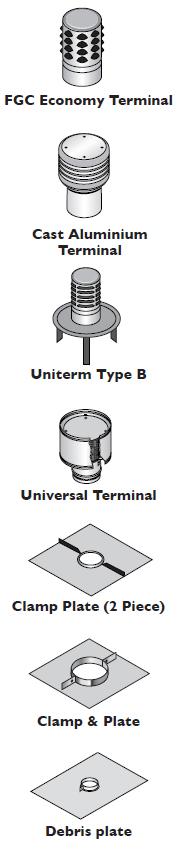
Debris Plate
The debris plate is used within the existing chimney stack, just above the base (see Fig. 4 opposite). The clamp fitting is used to fasten the plate to the flex and then the plate should be securely fastened within the chimney stack.
Connection to a Fluebox
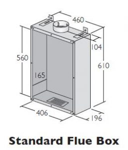 Standard Flue Box
Designed for use with radiant and decorative gas fires complying to BS 7977-1. Constructed with an aluminium liner and coated steel outer case.
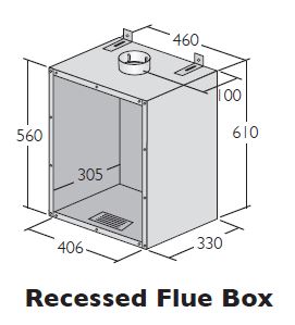 Recessed Flue Box
Designed with the spigot at the rear, for use with larger radiant and decorative gas fires. for gas fires to BS 7977-1.
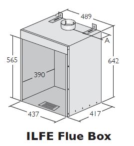 ILFE Flue Box
For use with Inset Live Fuel Effect gas fires complying to BS 7977-1, with a heat output not exceeding 7kw.
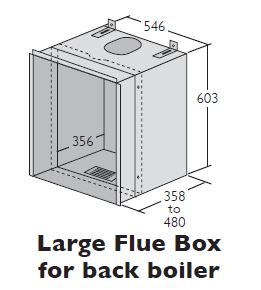 Large Flue Box for Back Boiler
Adjustable in depth from 358mm – 480mm to accommodate a wide range of back boilers. Suitable for fires complying with BS 7977-2. Universal opening allowing connection to the boiler with B Vent or Flex.
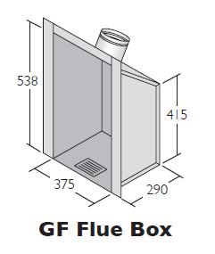 GF Flue Box
Single wall design with sloping back to help fit some openings. For radiant gas fires complying with BS7977-1.
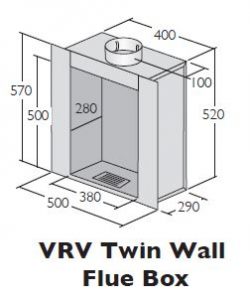 VRV Twin Wall Flue Box
Twin wall construction for reduced condensation. Otherwise as VRV Single Skin Box.
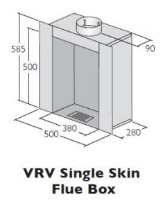 VRV Single Skin Flue Box
Suitable for fires complying with BS7977-1. Fits most popular radiant gas fires including the widely used Valor Firelite Oxysafe. Reduced height, extra depth and extra large flanges minimise builders work on installation.
Frequently Asked Questions
Can anyone install Flue Liner?
Connection to an appliance which is not connected to the fuel supply, should be carried out by a competent person. However, connection to an appliance that is connected to the fuel supply must be carried out by a GAS SAFE (for gas) or OFTEC (for oil) registered installer.We recommend the use of HETAS approved installers for solid fuel applications. If a non HETAS approved installer is used, then the installation must be signed off by a Building Control Inspector prior to being used.
Are there any special tools or equipment required?
No.The following would be necessary:- suitable cutting equipment, screwdriver, and adjustable spanner.To weather the top of the chimney stack and seal, a trowel with some sand and cement will be required. A closure plate would need to be fitted at the bottom of the system using appropriate fixings.
Can Flue Liner be installed anywhere?
No. Flue liner must only be installed inside a masonry brick chimney, as defined in the table on page 2 depending on the type and year of chimney construction.
Are any other materials required?
The connection to the appliance should be made using a high temperature sealant and/or glass rope to ensure a positive seal. Where TecnoFlex Plus is to be fitted to the top of an open fire place, a Schiedel Chimney Systems gather unit should be fitted into the throat of the chimney connected to the TecnoFlex Plus and sealed off.
The chimney has been previously used for an open solid fuel fire, can a flue liner be installed straight away?
No, in all cases, the chimney must be inspected for deterioration and if necessary, any remedial work required must be carried out. The chimney should be swept, preferably by a member of NACS (National Association of Chimney Sweeps) or a suitably qualified chimney sweep who would provide a certificate after sweeping and checking, which should be retained for future reference. A list of HETAS registered chimney sweeps can be found at www.hetas.co.uk
How is the liner supported?
Triplelock Flex is relatively light so it can be supported at the top of the chimney by using a clamp plate, which should be fixed to the top of the masonry stack.
TecnoFlex Plus however, is heavier and would be supported either by using a separate plate and clamp, which would be securely fixed to the top of the stack, or using a suitable pot hanger – see p.5 for more details.Where a tee is used at the base of the system to provide a drain point/cleaning access or connection to a flue pipe from the appliance, a bottom support bracket would be required, fixed to the inside of the stack.
How is the liner cut to the correct length for the chimney?
After the length of flue liner has been connected to the appliance, fluebox spigot or to the flue pipe connecting to the appliance, allow sufficient liner to protrude at the top of the chimney stack in the case of the pot hanger terminals, or above the top plate and clamp to ensure a positive location within the relevant terminal, and cut.This should be done by using an industrial knife or metal snips. At all times extreme care must be taken when cutting the liner and strong industrial gloves plus long sleeved overalls should be worn as cut edges are very sharp. In addition, any tape secured to the ends of the liner, which is provided for safe handling prior to installation, must be removed before completion, and commissioning of the full system.
Is there a correct ‘way up’ to install the flue liner?
Yes, on TecnoFlex Plus multifuel Iiner; the directional arrow on the outside of the liner indicates the direction of flue gases, and this must be pointing upwards towards termination.
Triplelock Flex can be installed either way up.
How should the Terminal be connected to the flue liner and how is the installation made weatherproof?
For gas and oil systems, the terminal should be fitted over the protruding end of the liner, ensuring that the flex does not protrude beyond the stop bead in the terminal, and riveted or secured using self tapping screws. On TecnoFlex Plus, where used on solid fuel appliances, either a proprietary chimney pot must be fitted by bedding the pot on to the top plate or, whilst technically an open terminal provides the least possible resistance to the flue gases, in order to prevent excessive rain ingress, a raincap or combined pot hanger and terminal may be used. Only 316L material is used on Schiedel’s terminals including raincaps, pot hangers and combined pot hanger and terminal to provide the highest corrosion resistance. In all cases, the top of the stack should then be weathered and sealed using a suitable acid resistant mortar to prevent ingress of water.
Are there any special requirements for providing combustion ventilation?
It is very important that sufficient air for combustion is provided to the room containing the appliance, to enable correct and efficient working of the system. Reference should be made to the appliance manufacturer’s instructions and recommendations are also given in the Building Regulations Document J.
Does an existing chimney need relining when fitting a gasfire into a fireplace opening?
Building Regulations Document J, outlines different requirements for relining masonry chimneys built before and after 1st February 1966.This can be summarised in the following table to provide guidance in the correct method of installing Schiedel Chimney Systems flue liners into these chimney types. The liner must be sized to meet the requirements of the new appliance, please refer to the flue size selection guide and the appliance manufacturer’s instructions. A lined chimney is defined as one which is fitted with a clay or concrete liner within the flueway, complying with Document J.
 What basic components are required for a typical relining system?
A typical installation would include the liner, a clamp plate and terminal. These are generally supplied in a kit form for Triplelock Flex, a debris plate would also be required to seal off the base of the stack. In the case of an open fire using TecnoFlex Plus, a gather unit, and debris plate would be necessary together with a top insert and a suitable terminal/ pot. When installing a flue liner for use on a gas fire complying to BS7977-1, BS7977-2 and BS EN 509 (i.e. Radiant, BBU, DGF or ILFE), a range of flueboxes are available with Triplelock Flex and TecnoFlex Plus spigots for use within the chimney opening.
When a roof has been converted from flat to pitched, and the existing chimney is capped, can the chimney be reused to accommodate a new appliance?
The chimney can be reused providing the existing brickwork is inspected to ensure it is in good condition.The chimney can be lined with the appropriate liner, ensuring that the liner is used only inside the stack. Extension from the top of the capped off stack should be made using a System Chimney approved to BS EN1856-1, such as Eco ICID or ICS. Connection from the appliance should be made using a connecting flue pipe approved to EN1856-2 such as Prima Plus for all fuels, or Prima Smooth in the case of solid fuel
Is the flexible liner pulled up or down the chimney, and what should be used?
The flue liner can be pulled up or down the chimney the chimney using a nose cone and string/rope. A nose cone can be purchased, rope attached, and connected to the end of the liner. The existing chimney has a flexible flue liner fitted, connected to an old gas fire.
If the fire was to be changed can the liner be reused for the new fire?
Yes, in general terms, providing the diameter and type of flex is suitable for the new appliance to be fitted, the installer has inspected the liner and is satisfied that the condition of the liner is such that it may be reused with the new appliance. However, as the lifespan of the previous appliance and liner may not be known, it is strongly recommended the old flueliner is removed, the chimney swept, then a suitable new liner installed.
Are there any other maintenance checks that should be carried out when installing a new appliance?
It will be necessary to check that the flaunching at the top of the stack is not cracked, and if so replaced.The brickwork pointing and the flashings should be checked to ensure they are weather tight and repaired where necessary.
Can flue liner be used on condensing appliances?
We recommend the use of TecnoFlex Plus on condensing Gas and Oil appliances. The smooth inner liner allows for the swift drain down of condensates to a suitable drain point at the base of the vertical system.TecnoFlex Plus can be used on appliances with a maximum pressure of 200Pa.The liner should be used in combination with connecting flue pipe and fittings, which have been tested and approved to BS EN1856-2. An acid resistant sealant, such as Rotempo or equivalent should be used to seal the joint between the flexible liner and the screw fit adaptor.
The chimney to be lined is very tall, can lengths of flue liner be joined?
It is recommended that flexible flue liners be installed in continuous lengths without joiners. Schiedel Chimney Systems can supply all flue liners in specific lengths on drums or in pack form upon request. On TecnoFlex Plus installations, joiners are only permitted where the chimney liner length exceeds the maximum length available and details of the installation are agreed in advance, in writing, in compliance with product warranty conditions.
Multi-Fuel Applications
Multi-Fuel refers to an appliance which may be used to burn either seasoned wood, with a maximum moisture content of 20%, or approved solid fuels.These fuels must not be mixed, as this increases the risk of deposits being built up in the liner.
Do I require an appliance connector to fit the flex to the appliance spigot?
In the event of connecting directly to the appliance i.e a gas fire with back boiler within the chimney stack, it will generally be unnecessary to use an appliance connector. When making a connection to a connecting flue pipe in another product type, then the appropriate connector to/from flexible would be used. In all cases, a gas tight joint must be ensured.
Will the flue liner be OK to use after a chimney fire?
The flue liner could be damaged under the conditions of a chimney fire, and must always be inspected by a suitably qualified individual (e.g. HETAS registered installer and replaced as necessary), before using the appliance or fire again.
AFTER INSTALLATION
Testing and Commissioning prior to first use
This is carried out using a flue flow test as described in BS EN 15287 Parts 1 & 2, with reference to the appropriate appliance type.
Appliance Operation
If the appliance is slumbered overnight or for longer periods then it is advisable to run the appliance at controlled high fire condition for a period of at least 30 minutes. Prolonged slumbering of the appliance is a contributing factor to a liner failure. It is important to maintain sufficiently high flue gas temperatures in order to avoid condensate and acid corrosion problems, and to ensure complete combustion of the fuel.
Maintenance
Each chimney must be designed to allow for easy inspection; sweeping should be carried out by competent persons. On solid fuel applications a list of HETAS registered sweeps can be found at www.hetas.co.uk.
Chimney flue cleaning and inspection require the use of appropriate tooling – under no circumstances should chemical cleaners or mild steel tools be used to sweep stainless steel chimneys. Cleaning/inspection of any chimney system should be carried out at least once a year, along with maintenance of the appliance, but it is recommended that chimneys serving solid fuel appliances be swept at least twice a year, at the end of the heating season to remove any deposits, which may have built up during the season, and prior to the start of the next heating season to ensure that the the flue way is clear of any blockages such as birds nests etc.
We would advise that monthly checks are carried out to ensure that there is no build up of any deposits in the flue way between appliance and system chimney or chimney liner.
Fuel Storage and Usage
Where solid fuels are being used, correct storage is critical and fuels must be kept dry. Wood must be seasoned prior to use, with a maximum moisture content of 20%. Only approved fuels should be used. Refer to HETAS list for details on.The fuel used must be suitable for the appliance – please refer to manufacturer’s instructions.
NOTICE PLATE
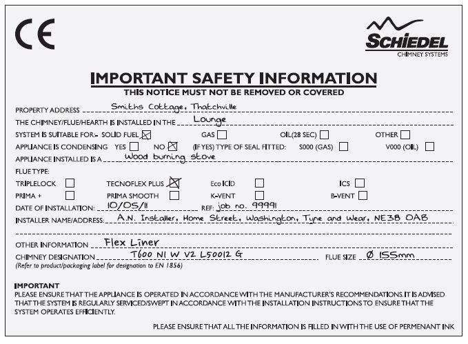 Notice Plate for Flexible Liner Product
The Notice plate should be marked up in indelible ink and securely fixed in an unobtrusive but obvious position within the building such as:
- Next to the electricity consumer unit.
- Next to the chimney installation described.
- Next to the water supply stop-cock.
PRODUCT GUARANTEE
What is the life expectancy and are there any guarantees on the liners?
We are confident in our products and so offer you (the owner) a generous guarantee in relation to the flexible liner system (the System). Provided that you comply in full with Your Responsibilities and subject to the Small Print, we guarantee to you that the System will be free from defects for whichever is the greater of:
- a period equal to the guarantee period of the appliance to which the Liner is first connected; or
- 20 years.
In the unlikely event that the System becomes defective during the guarantee period, we will provide a like-for-like replacement for free (subject to your compliance with Your Responsibilities and subject to the Small Print). If the same model is no longer available, we will replace it with a suitable alternative. When we say ‘no quibbles’ we mean it and so the guarantee we offer is a straightforward one; we’ve set out below what is covered and what isn’t by the guarantee as well how to ensure you benefit from it.
Your Responsibilities
To benefit from our guarantee, you must:
- Register your product within 30 days of installation at www.schiedel.co.uk and provide us with any evidence we reasonably request to prove that your System has been fitted by a HETAS approved installer or if not, has been signed off by a Building Control Inspector prior to use.
- Familiarise yourself with the User Guide and comply with its provisions in full during the lifetime of your usage of the Liner (including by keeping the required records safe). Failure to do so will invalidate any guarantee claim.
How to claim under your guarantee
To claim under your guarantee, please email us at info@schiedel.co.uk (please note: November onwards visit our website to claim your guarantee).You will be asked to provide proof that you have complied in full with the User Guide (for example, by providing cleaning records) and we will then assess your claim, keeping you fully informed.
Terms & Conditions (Small Print)
Please be aware of the following:
- Your guarantee is effective from the date on which your System is installed.
- The guarantee extends only to us providing you with a replacement System. We will pay for the delivery of that replacement to the address you have registered but you are responsible for any costs related to the removal and transit of the defective System and the installation (and any associated costs) of the replacement System.
- The guarantee does not apply to the extent that defects in a System arise as a result of: (1) use of fittings other than approved fittings; (2) any failure to comply with the instructions set out in the User Guide (including those instructions relating to care and servicing of your System); (3) any alteration or repairs you make to it (or are made on your behalf) without our express written permission; (4) any accidental damage suffered during transit or otherwise; (5) any damage to the System that arises as a result of the installation of the System (our guarantee is offered in respect of the System product alone and does not cover the workmanship of any installation services you may obtain from any third party); or, (6) any negligent or other improper use.
- If we replace your System under this guarantee, the guarantee period will not be extended.
- If you move house, you may transfer the benefit of the remaining period of the guarantee to the new home owner within 3 months of the change of ownership. It is your responsibility to transfer the guarantee by emailing us at info@schiedel.co.uk (please note: November 2015 onwards you will need to amend the gurantee on our website) and to notify the new owner of the terms of the guarantee (including the new owner’s responsibilities). A failure to notify us of a transfer within the timescales will invalidate the guarantee.
- Where you claim that a System is defective, we reserve the right
- (1) to carry out any tests on that System, and/or
- (2) to require access to that System, in both cases to satisfy ourselves that you have complied in full with your responsibilities (including by adhering to the User Guide) and that your claim is valid. Please cooperate with any reasonable requests we make in this regard.
- This guarantee is offered in addition to your legal rights as a consumer.
For any help to register, claim or amend your guarantee please contact our offices;
Schiedel Chimney Systems, Crowther Estate, Washington,Tyne & Wear, NE38 0AQ. Tel: +44 (0)191 416 1150.
Product Registration
We have upgraded our guarantee registration system. This is only available online. Visit www.schiedel.co.uk to register.
If for any reason you are unable to register online, please contact our offices and a paper version will mailed to you.
Please Note: An incomplete registration could make your warranty void.