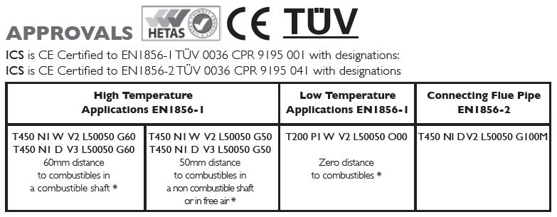
* For full information please see Distance to Combustibles Section
- Manufactured under a Quality Management Scheme approved to BS EN ISO 90014 Hour Fire Rating to BS476 Part 20
- Certified for corrosion resistance on gas, oil and solid fuel by Gastec, MPA and TÜV
- HETAS listed for use on solid fuel applications.
Mandatory Requirements
Connection to an appliance which is not connected to the fuel supply, should be carried out by a competent person. We recommend the use of HETAS approved installers for solid fuel applications. If installation is carried out by a non HETAS registered installer, the installation must be certified by a local Building Control inspector. Connection to an appliance that is connected to the fuel supply must be carried out by a Gas Safe (Gas) or OFTEC (Oil) registered installer.
The design guide must be read in conjunction with the detailed component installation instructions. For full design and installation details the key referral documents are:
-
BS EN 1856-1: Chimneys – System Chimney Products
-
BS EN 1856-2: Connecting Flue Pipes
-
BS EN 1859: Metal Chimneys – Testing Methods
-
BS EN 1443: Chimneys – General Requirements
-
BS EN 15287-1: Chimneys. Design, installation and commissioning of chimneys. Chimneys for non-room sealed heating appliances.
-
BS 5440-1: Fluing and ventilation for gas appliances of rated input not exceeding 70kW net (1st, 2nd and 3rd family gases). Specification for installation of gas appliances to chimneys and for maintenance of chimneys.
-
Approved Document J: – Combustion appliances and fuel storage systems (England & Wales)
-
DFP Technical Booklet L: – Combustion appliances and fuel storage systems (NI)
-
Technical Handbook (Domestic & Non Domestic), Section 3 – Environment (Scotland)
-
Appliance Installation Instructions and related standards. Other standards covering specific applications will also be relevant and must be adhered to.
Planning permission may be required, and reference should be made to the local Building Control Department.
Ensure all chimney components are available and check them to ensure there has been no damage. Do not use damaged components. Build the chimney up through the previous designed route which should be as straight as possible.
PRIOR TO INSTALLATION
Ventilation
It is very important that sufficient air for combustion and ventilation is provided to the room containing the appliance, to enable correct and efficient working of the appliance and chimney system. Reference should be made to the appliance manufacturer’s instructions and recommendations are also given in the Building Regulations Document J, CIBSE guidance notes and BS 5440.
Carbon Monoxide Alarms
The carbon monoxide alarms should comply with BS EN 50291
Where a new or replacement fixed solid fuel appliance is installed in a dwelling, a carbon monoxide alarm must be provided in the room where the appliance is located.
Please follow manufacturer’s instructions with regards to siting and fixing or alternatively :-
-
On the ceiling at least 300mm from any wall or if it is located on a wall, as high up as possible (above any doors and windows), but not within 150mm of the ceiling and
-
between 1m and 3m horizontally from the appliance.
N.B Provision of a carbon monoxide alarm should not be regarded as a substitute for correct installation and regular servicing.
Painting
If painting of any external sections is required, it is important to de-grease, dry and prime the exterior surface prior to the application of appropriate heat resistant paint. Schiedel Chimney Systems can provide to special order, chimney sections and accessories painted to an extensive range of British Standard RAL colours – details on application.
Handling
It is advised that suitable PPE should be used when handling the products.
Delivery to Site and Storage
Components should be carefully transported and off loaded.They should be inspected to ensure they have not been damaged, and should be stored off the ground and under cover so that they are protected from accidental damage and the adverse effects of weather.
CONNECTING FLUE PIPE
Appliance/Chimney Connection
Connection to the appliance can be made using Prima Smooth, Prima Plus or alternative approved single wall connecting flue pipes, or ICS.
This must be done by using the appropriate appliance connector. When a single wall connecting flue pipe is used to connect an appliance to the chimney, the lower end of the chimney section must extend a minimum of 425mm below the ceiling. When connecting the appliance to the flue pipe all joints between the flue pipes/appliance outlet must be securely caulked and sealed with non asbestos rope (or suitable alternative) and fire cement on solid fuel appliances and using the appropriate lip seal gasket in the case of condensing appliances.
Any flue pipe connection to the chimney MUST be made in the same room as the appliance.
Connection to Draught Diverter
Where the appliance features a draught diverter the connection should rise vertically from it for at least 600mm before any change of direction (unless otherwise specified by the appliance manufacturer). This is in accordance with the recommendations contained in BS 5440 Part 1 section 4.1.5.
Connecting Flue Pipe Diameter
The chimney size should be as recommended by the appliance manufacturer. Where there is a requirement for a flue diameter smaller than the appliance spigot, then the operational requirements of the appliance and the configuration of the flue must satisfy the flue sizing requirements of EN13384-1 for single appliances, and EN13384-2 for multi appliances.
Distance to Combustibles
In accordance with building regulations, it is essential that the correct distance to combustible material is maintained on connecting flue pipes. On solid fuel applications, where there is a risk of soot fire, on unmeasured (NM) designated single wall product, this distance is 3 x ØInt of the pipe, e.g. for Ø130mm the distance is 390mm and for Ø150mm the distance is 450mm to combustibles on both painted and non painted variants. On measured (M) single wall or double wall products this distance will be as declared by the chimney manufacturer. On ICS25, when used as a connecting flue pipe, this distance has been measured and is set at 100mm.
Connecting Flue Pipe Route
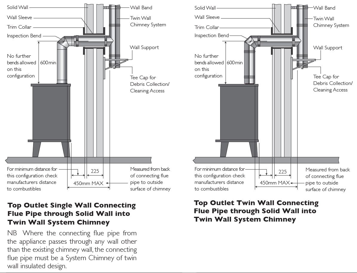
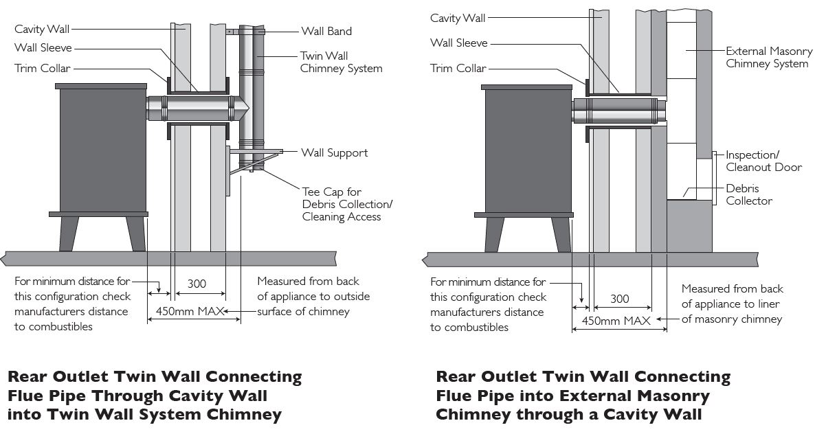
Single wall connecting flue pipes should only be used to connect appliances to a Chimney.They should not pass through any roof space, partition, internal wall or floor, except to pass directly into a chimney through a wall of the chimney.
Connecting flue pipes should be located as to avoid igniting combustible material.
On solid fuel appliances the maximum length of a connecting flue pipe is 2m. This distance is reduced to 1.5m if any of the acceptable alternative methods of connection are adopted as per BS EN15287-1. (See p.5-6 for full details.)
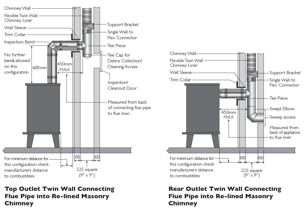
On appliances with a top outlet, it is recommended that a vertical run of at least 600mm should be allowed immediately above the appliance prior to any change of direction.
On appliances with a rear outlet, it is recommended that there is maximum of 150mm in the horizontal run however under certain conditions, as described in alternative methods in BS EN 15287-1, this may be increased to 450mm. (See p.5-6 for full details.)
Within a system (Chimney + Connecting Flue Pipe) there should be no more than 4 changes of direction of maximum 45˚. 90˚ Factory made bends or tees within the system may be treated as being equal to two 45˚ bends (as per Document J of the Building Regulations issued October 2010).
Inspection
On solid fuel applications to conform to Building Regulations, provisions should be made to enable a chimney to be inspected and cleaned.
An inspection pipe, inspection elbow or a 90° or 135° Tee with tee cap can form a suitable inspection point (unless cleaning/inspection can be done through the appliance). To aid cleaning, sufficient distance should be left between changes of direction to permit the safe passage of cleaning brushes within the system. This is particularly important on solid fuel applications. It is recommended that chimneys serving solid fuel appliances be swept as frequently as necessary, but at least twice a year.
BS EN 15287-1 ACCEPTABLE ALTERNATIVE METHODS OF CONNECTION
Where a horizontal connecting flue of more than 150mm is required to connect a solid fuel fired appliance to a chimney, an installation method as per the examples below may be used provided the following criteria is met:-
-
The maximum length of horizontal connecting flue pipe does not exceed 450mm;
-
A Defra exempt appliance or an appliance, which is limited to burning authorised smokeless fuel only, is installed;
-
A calculation according to BS EN13384-1 has indicated safe operation of the proposed configuration, and the results of the calculation are left with the householder along with the appliance installation instructions;
-
The appliance manufacturer agrees in writing to the proposed configuration;
-
The chimney manufacturer agrees in writing to the proposed configuration;
-
The total length of single wall connecting flue pipe is not more than 1.5m;
-
The appropriate distances to combustible materials from both the appliance and the connecting flue pipe are maintained.
SYSTEM CHIMNEY
Chimney Diameter
The chimney size should be as recommended by the appliance manufacturer. Where there is a requirement for a flue diameter smaller than the appliance spigot, then the operational requirements of the appliance and the configuration of the flue must satisfy the flue sizing requirements of EN13384-1 for single appliances, and EN13384-2 for multi appliances.
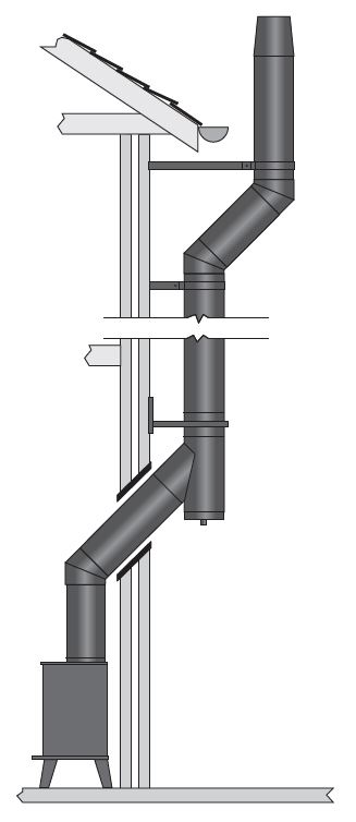
Chimney Route
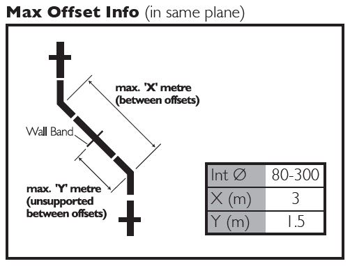
The chimney should remain as straight as possible through its vertical run to assist flow. Should it be necessary to offset a chimney run then the following guidelines should be adhered to:
It is recommended that a vertical run of at least 600mm should be allowed immediately above the appliance prior to any change of direction.Within a system, on all fuels, there should be no more than 4 changes of direction of maximum 45°. Factory made 90° bends or tees within the system may be treated as being equal to two 45° bends (as per Document J of the Building Regulations issued October 2010).
Connection to Draught Diverter
Where the appliance features a draught diverter the connection should rise vertically from it for at least 600mm before any change of direction (unless otherwise specified by the appliance manufacturer). This is in accordance with the recommendations contained in BS 5440 Part 1 section 6.1.4
Direct Connection Appliance to System Chimney
When connecting from the appliance directly to a system chimney, the appropriate appliance connector must be used and the joint between the appliance spigot and the appliance connector must be securely caulked and sealed with non asbestos rope (or suitable alternative) and fire cement on solid fuel appliances.
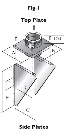
Distance to Combustibles
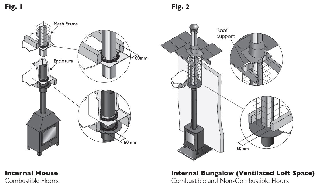
In accordance with building regulations, it is essential that the correct distance to combustible material is maintained. On solid fuel applications, where there is a risk of soot fire, a distance of 60mm to combustibles must be maintained within a combustible floor and within a combustible shaft (see Fig.1 below).There is no need to line the area within the floor cavity with plasterboard; however the ventilated fire stop plate and ventilated support plate must be used.
On gas and oil applications, a distance of 50mm to combustibles must be maintained within a combustible floor and within a combustible shaft.The ventilated fire stop plate and ventilated support plate must be used.
Where the chimney penetrates a non combustible floor and where a non combustible shaft is used, a distance of 50mm to the shaft is sufficient. In this case, non ventilated fire stop plates and support plates may be used with a ventilated fire stop being used where the chimney penetrates into the roof space.
On bungalow applications where the chimney runs through either a combustible or non-combustible ceiling, an unventilated bungalow fire stop plate kit can be used. Please note that an unventilated support plate can not be used above the ceiling in this case.The weight of the chimney should be supported using the roof support (see p.19). Distance to combustibles must be respected within the ceiling space (see Fig. 2 below) and mesh frame should be used within the loft space, which must be ventilated (see Fig. 2 below).
Enclosure/Shafts
With the exception of the room containing the appliance, where the chimney passes through any part of the building, where there is a risk of accidental human contact, i.e a bedroom etc., or where there is a risk of contact with combustible materials stored in a cupboard or in the roof-space, the chimney must be enclosed in an appropriate way to meet Building Regulations. This can be achieved by boxing in the chimney in habitable rooms, or by the use of a protective wire mesh frame in roof spaces etc. In all cases the minimum distance to any combustible material, including loft insulation, must be respected according to the table on p.1, and any enclosure should be ventilated using the appropriate ventilated fire stops.
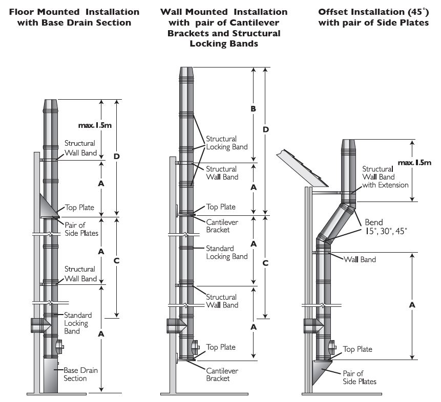
Support Components
The weight of a chimney system is considerable and requires independent support. Minimal weight should be borne by the appliance.The weight of the chimney can be supported from floor level by using a base support plate, or floor support; from the wall by using wall support top plates together with side plates or cantilever brackets; or from first floor level by using a support plate and clamp fixed to the floor/ceiling joists.
Wall brackets are non load bearing and provide lateral support only. Refer to the load bearing tables for full details of maximum loadings.
Where the flue is freestanding above the roof and its height exceeds 1.5m above the last support or above the roof, a height of up to 3m can be achieved unsupported using the extended locking bands at the joint immediately below the last support and on each pipe joint above the last support.
Alternatively guy wire brackets can be used at the 1.5m level and every 1.5m thereafter in conjunction with guy wires, or rigid stays (provided by others).
Chimney Termination
For full information regarding to chimney termination, please refer to Annex M of BS EN 15287-1. A
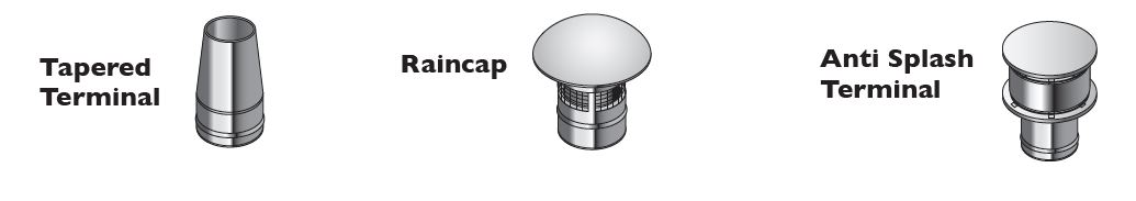
Terminals
All terminals must be secured with the use of a locking band. On solid fuel appliances, an open termination is normally recommended. However in certain conditions, rain caps or anti-downdraught terminals may be used.
Rain caps and anti-downdraught terminals are available in three versions, with anti-bird mesh, with spark guard, or without mesh. Where a terminal with mesh is used, there is a risk of soot build up, and therefore regular cleaning is required to avoid blockage, particularly when using oil or solid fuel.
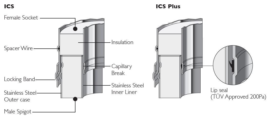
Jointing System
All joints in the ICS chimney range, which require a locking band, are made by means of a simple push fit jointing method. This is achieved by the engineered spigot and socket system having a pronounced lead-in-edge to ease assembly.
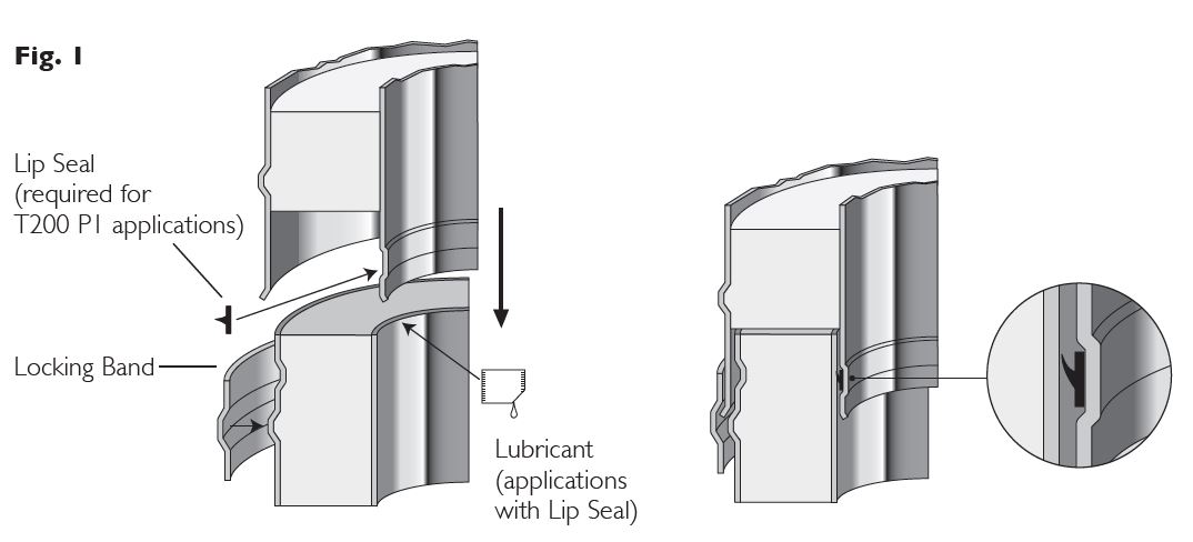
ICS Plus is created by adding a lip seal gasket into the inward bead on the liner of the standard components, which are suitable for use in condensing applications with a P1 designation. When installing ICS Plus components, Gaskets should be fitted dry and lubricant applied to the internal of the female liner socket
Standard Chimney Sections (Pipes, Tees and Elbows)
Before assembling chimney sections, slip a locking band over female socket of the chimney section. Ensure the sections are pushed tightly together, before securing the locking band by use of the quick release clip. The clip can then be tightened into place by using the tightening bolt. Note:-joints must NOT occur within floor or ceiling spaces.
All flue gas carrying components must be installed with the direction arrow on the product label pointing to termination with the external male spigot of the case uppermost.
Locking Band (supplied with each component with a female socket on the case)
A locking band must be fitted to every joint in the system.The band is of stainless steel construction and is fitted with a quick release clip and a stainless steel tightening bolt.The bolt can be adjusted to ensure the joint is firmly secured.
Structural Locking Band
The structural locking band, which is purchased separately, is used instead of a standard locking band in a situation where extra structural support is required, for instance where the chimney height is >1.5m above the last support or above the roof. It is also used to provide extra support in long horizontal runs. A maximum of 3m unsupported height can be achieved by fitting the structural locking band on the joint immediately below and on every joint above the last support.
Appliance Connector/Starting Connector/Stove Starter Pipe
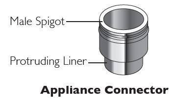 The protruding liner of these components should be pushed into the appliance
spigot with the external male case spigot pointing upwards.
On solid fuel appliances the appliance connector should be sealed to the appliance with fire rope and fire cement or high temperature sealant to provide a gas tight joint. On condensing appliances the appropriate lip seal should be used.
Adaptors from Prima Plus & Prima Smooth to ICS
These components are used to convert from a single wall connecting flue pipe to the ICS system chimney. The protruding liner should be pushed down inside the female socket of the connecting flue pipe, with the double wall external case spigot pointing in the direction of the flue gases.
Adaptor to Flex/TecnoFlex Plus
This component is used to convert from ICS to Flex/TecnoFlex Plus. The Flex/TecnoFlex Plus is pushed down inside the upstand on the adaptor, secured using self tapping screws and sealed with fire cement and fire rope to provide a gas tight joint.
Adaptor from ICS to Prima Plus
This component is manufactured with an ICS female socket and a Prima Plus female socket, and is used where there is a requirement to convert from ICS to Prima Plus. The ICS female socket should be attached to the previous ICS component and the joint secured using the locking band provided.
Increaser
This component is used to increase from one diameter to the next diameter (e.g.) 200mm to 230mm.The component is fitted in the same way as a standard pipe length and should be secured with the locking band provided.
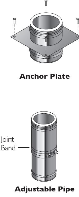 Anchor Plate
When commencing an installation with a fire chest, hood or similar an anchor plate with plain end should be used. When extending an existing brick or masonry chimney stack, an anchor plate must be used which needs to be lined with a TecnoFlex Plus Liner then the anchor plate with the screw fit connection should be used .
The liner of the Anchor Plate should be pushed into the opening of the fire chest with the plate resting on a bed of fire cement.The plate should then be fixed onto the concrete slab by masonry screws fitted through the pre-drilled holes in the plate.
In the case of a chimney extension, the liner of the anchor plate fits down inside the existing chimney stack. If aTecnoFlex Plus chimney liner is being used then the anchor plate is secured to the liner by twisting in a clockwise direction.The plate should then
be then be bolted to the top of the existing chimney and sealed using fire cement.
Adjustable Pipe
The adjustable pipes are delivered as two pre-assembled sections with a joint band and locking band (see Fig.1).They are used with standard components to achieve an exact length on site and avoid on-site cutting of components.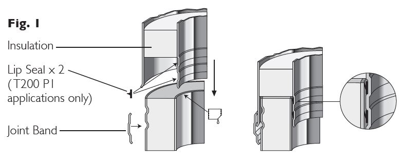
- Calculate the length required. Loosen the joint band and remove the top section of the adjustable pipe.
- Remove insulation as required to achieve the correct length.
- Re-assemble the pipe and cover the joint with the joint band.
- Fix the adjusted section to standard components using the locking band provided. Please note that the adjustable pipe is non load bearing.
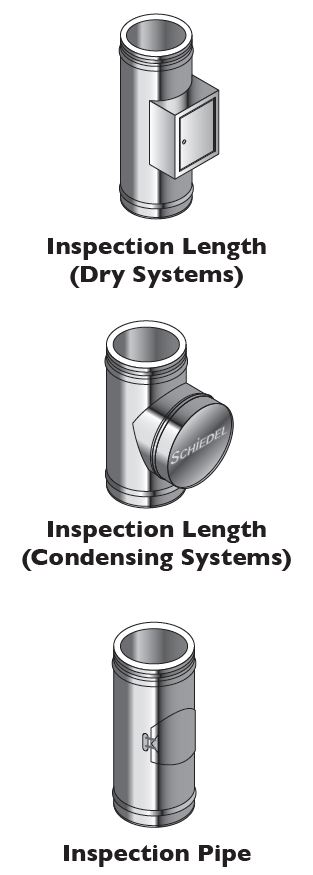 Inspection Length (Dry Systems)
The inspection length is a component providing the facility for flue inspection and cleaning. It is installed as per a standard pipe section.
Inspection Length (Condensing Systems)
The inspection length is a component providing the facility for flue inspection and cleaning on condensing or high efficiency appliances with a maximum flue gas temperature of 250°C, and a positive pressure rating of up to 200 Pa. It is installed as per a standard pipe section.
Inspection Pipe
The Inspection pipe is a component which provides the facility to inspect the flue. It is installed as per a standard pipe section.
Measure Pipe
The measure pipe is a component which provides access to the flue for draught testing or for flue gas analysis. It is installed as per a standard pipe section.
Vertical Drain Pipe
This component is used on condensing systems and provides the facility to collect and drain off condensate from the chimney. It is installed in the same way as a standard pipe. It is provided as standard with a 3/4” BSP fitting.
SW-DW Adjustable Starter Section
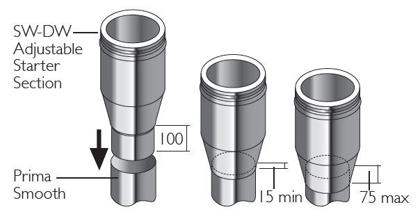
This maximum length of 75mm will leave sufficient space within the adaptor to allow for thermal expansion of the single wall pipe and also to allow for the connecting flue pipe to be removed without cutting, if the appliance has to be moved for servicing.
Elbows and 90˚ Inspection Elbows
For offset information on standard elbows, please refer to p.14
Please note that 90° Inspection bends may be incorporated into a connecting flue pipe arrangement on all fuels, please refer to National Annex of BS EN 15287-1 for specific guidance re use on solid fuel applications, the diagrams on p.5-6 give guidance.
In cases of top mounted stoves, a minimum vertical height of 600mm from the appliance must be respected prior to any change of direction in the flue pipe.
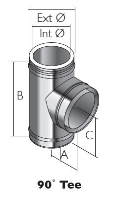 90˚ Tee
This component may be used to connect from a connecting flue pipe to the vertical system chimney at 90° or the branch may be used to locate a draft stabiliser. It is installed as per a standard pipe section.
|
Int Ø |
80 100 130 150 180 200 230 250 300 | ||||||||
|
Ext Ø |
130 150 180 200 230 250 280 300 350 | ||||||||
|
A |
145 155 170 180 195 205 220 230 258 | ||||||||
|
B |
250 270 305 325 355 375 405 425 480 | ||||||||
|
C |
145 |
155 |
170 |
180 |
195 |
205 |
220 |
230 |
258 |
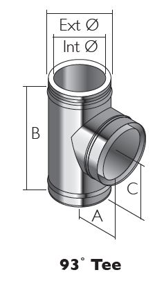 93˚ Tee
This component must be used in place of a 90° tee to connect from a connecting flue pipe to the vertical System Chimney on condensing systems to ensure that condensate can drain down through the system to a drain point.This component is installed as per a standard pipe section.
|
Int Ø |
80 100 130 150 180 200 230 250 300 |
|
Ext Ø |
130 150 180 200 230 250 280 300 350 |
|
A |
– 162 178 189 206 216 233 244 264 |
|
B |
– 278 309 329 359 379 405 455 490 |
|
C |
– 166 178 189 206 216 233 257 268 |
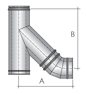
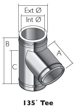 135˚ Tee
This component may be used in combination with a 45° elbow to connect from a connecting flue pipe to the vertical system chimney. It is installed as per a standard pipe section and provides the least resistance to the flow of the flue gases.
|
Int Ø |
80 100 130 150 180 200 230 250 300 | ||||||||
|
Ext Ø |
130 150 180 200 230 250 280 300 350 | ||||||||
|
A |
– 262 298 322 358 382 419 443 509 | ||||||||
|
B |
– 327 375 403 445 474 516 544 622 | ||||||||
|
C |
– |
262 |
298 |
322 |
358 |
382 |
419 |
443 |
509 |
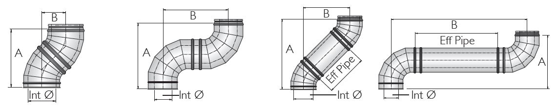
Offset Dimensions (made by assembling 2 bends)
 Offsets for Double 15˚ Bend
|
Int Ø |
80 |
100 |
130 |
150 |
180 |
200 |
230 |
250 |
300 |
|
A |
295 |
295 |
295 |
295 |
315 |
315 |
315 |
334 |
334 |
|
B |
39 |
39 |
39 |
39 |
41 |
41 |
41 |
44 |
44 |
Offsets for Double 30˚ Bend
|
Int Ø |
80 |
100 |
130 |
150 |
180 |
200 |
230 |
250 |
300 |
|
A |
280 |
299 |
327 |
336 |
355 |
373 |
373 |
392 |
411 |
|
B |
75 |
80 |
88 |
90 |
95 |
100 |
100 |
105 |
110 |
Offsets for Double 45˚ Bend
|
Int Ø |
80 |
100 |
130 |
150 |
180 |
200 |
230 |
250 |
300 |
|
A |
307 |
324 |
341 |
358 |
376 |
393 |
427 |
427 |
461 |
|
B |
127 |
134 |
141 |
148 |
156 |
163 |
177 |
177 |
191 |
Offsets for Double 90˚ Bend
|
Int Ø |
80 |
100 |
130 |
150 |
180 |
200 |
230 |
250 |
300 |
|
A |
300 |
316 |
348 |
366 |
396 |
420 |
452 |
468 |
518 |
|
B |
300 |
316 |
348 |
366 |
396 |
420 |
452 |
468 |
518 |
Offsets for 135 Tee˚ & 45˚ Bend
|
Int Ø |
80 |
100 |
130 |
150 |
180 |
200 |
230 |
250 |
300 |
|
A |
343 |
370 |
437 |
445 |
452 |
496 |
523 |
537 |
592 |
|
B |
305 |
324 |
404 |
406 |
415 |
473 |
475 |
499 |
556 |
Double 15˚ Bend C/W Pipe Length
|
Int Ø mm |
80 |
100 |
130 |
150 |
180 |
200 |
230 |
250 |
300 |
|
|
955 Eff Pipe |
A B |
1218 286 |
1218 286 |
1218 286 |
1218 286 |
1238 288 |
1238 288 |
1238 288 |
1257 291 |
1257 291 |
|
455 Eff Pipe |
A B |
735 157 |
735 157 |
735 157 |
735 157 |
755 159 |
755 159 |
755 159 |
774 162 |
774 162 |
|
205 Eff Pipe |
A B |
493 92 |
493 92 |
493 92 |
493 92 |
513 94 |
513 94 |
513 94 |
532 97 |
532 97 |
|
150 Eff Pipe |
A B |
445 79 |
445 79 |
445 79 |
445 79 |
465 81 |
465 81 |
465 81 |
484 84 |
484 84 |
Double 30˚ Bend C/W Pipe Length
|
Int Ø mm |
80 100 130 150 180 200 230 250 300 | |
|
955 Eff Pipe |
A B |
1107 1126 1154 1163 1182 1200 1200 1219 1238
553 558 566 568 573 578 578 583 588 |
|
455 Eff Pipe |
A B |
674 693 721 709 765 765 784 784 793
303 308 316 318 323 328 328 333 338 |
|
205 Eff Pipe |
A B |
458 477 505 514 533 551 551 570 589
178 183 191 193 198 203 203 208 213 |
|
150 Eff Pipe |
A B |
414 433 461 470 489 507 507 526 545
153 158 166 168 173 178 178 183 188 |
Double 45˚ Bend C/W Pipe Length
|
Int Ø mm |
80 |
100 |
130 150 180 200 230 250 300 | |
|
955 Eff Pipe |
A B |
982 802 |
999 809 |
1016 1033 1051 1068 1102 1102 1136
816 823 831 838 852 852 866 |
|
455 Eff Pipe |
A B |
629 449 |
646 456 |
663 680 698 715 749 749 783
463 470 478 485 499 499 513 |
|
205 Eff Pipe |
A B |
452 272 |
469 279 |
486 503 521 538 572 572 606
286 293 301 308 322 322 336 |
|
150 Eff Pipe |
A B |
417 237 |
434 244 |
451 468 486 503 537 537 571
251 258 266 273 287 287 301 |
Double 90˚ Bend C/W Pipe Length
|
Int Ø mm |
80 |
100 |
130 |
150 |
180 |
200 |
230 |
250 |
300 |
|
|
955 Eff Pipe |
A B |
296 1251 |
315 1270 |
345 1300 |
366 1321 |
415 1370 |
414 1369 |
445 1400 |
464 1419 |
518 1473 |
|
455 Eff Pipe |
A B |
296 751 |
315 770 |
345 800 |
366 821 |
415 870 |
414 869 |
445 900 |
464 919 |
518 973 |
|
205 Eff Pipe |
A B |
296 501 |
315 520 |
345 550 |
366 571 |
415 620 |
414 619 |
445 650 |
464 669 |
518 723 |
|
150 Eff Pipe |
A B |
296 446 |
315 466 |
345 495 |
366 516 |
415 565 |
414 564 |
445 595 |
464 614 |
518 673 |
FIRESTOP COMPONENTS
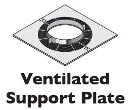 Ventilated Support Plate (Galvanised with S/S Band)
The support plate is used where the chimney passes through a combustible floor, and the weight of the chimney has to be taken at floor level. The support plate must be firmly fixed by using bolts or screws.
- Frame a four sided level square opening within the joists using timber stringers where necessary to allow for the correct distance to combustibles from the outer wall of the chimney.This distance must be a minimum of 50mm on Gas and Oil applications and 60mm for solid fuel applications (see Fig. 3 below – distance x).
- Lower the chimney section through the opening in the floor, and secure to the next section of pipe.
- Locate the two halves of the support plates around the chimney section, and secure to the joists using screws or bolts.
- Remove the screws which are fastened to the clamp band.Then fasten clamp band around the chimney section and position on top of the plate.Tighten using the nuts and bolts provided.
- Using the holes in the clamp support ring drill 3mm holes in the outer casing of the chimney section (drill bit should be set for a depth no greater than 10mm to avoid damage to the liner).
- Using the screws provided secure the clamp support ring to the outer casing of the chimney section.
Note: Joints must NOT occur within the floor or ceiling joists.
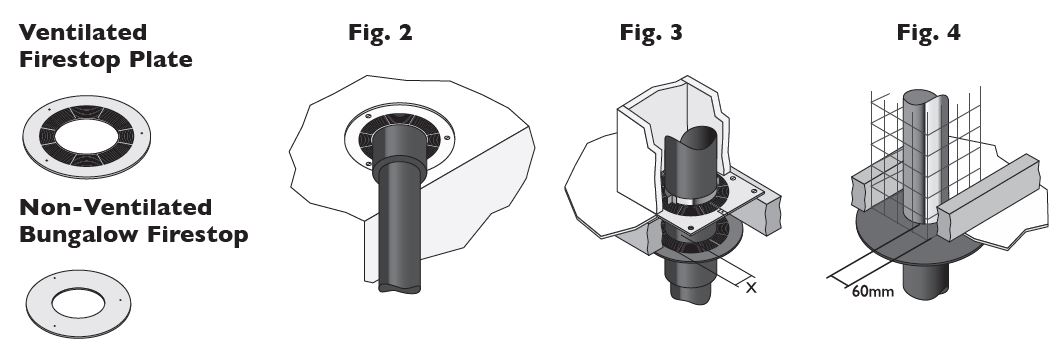
Ventilated Firestop Plate (1 & 2-Piece Round and 2-Piece Rectangular)
The ventilated fire stop plates are used in combination with standard ICS pipes where the chimney passes through a combustible floor or ceiling. The outermost circle of ventilation slots gives a distance to combustibles of 60mm. This measures the required distance for solid fuel applications. For gas and oil applications a minimum of 50mm is required, which should be measured on site. The fire stop plate should be positioned around the chimney and fastened to the pre-cut plasterboard or to the timber frame with nails or screws using the location holes provided (see Fig. 2 above).
Non-Ventilated Bungalow Firestop (1 & 2-Piece Round and 1-Piece Rectangular) Installed as per a ventilated firestop using the location holes provided (see Fig.4 above). Distance to combustibles must be respected – see p.8 for further info.
Support Plate with S/S Clamp Band (Non Combustible Floor)
The support plate is used where the chimney passes through a non combustible floor, and the weight of the chimney has to be taken at floor level. The support plate must be firmly fixed to the floor using bolts or screws provided by others. For load bearing Data refer to table further down below.
Fire stop Plate (Non Combustible Floor)
This fire stop plate is used exclusively where the chimney passes through a non combustible floor. The two halves of the plate are located around the chimney section and fastened to the floor using bolts or screws provided by others.
SUPPORT COMPONENTS
 Wall Band ( 60mm) Internal and External Application
The wall band is supplied in three parts, two stainless steel split bands which fit tightly around the outside of the chimney and a stainless steel back bracket. The parts are joined together by means of the nuts and bolts provided.The use of the item maintains a fixed distance of 60mm depending on the wall band type chosen from the outer casing of the chimney to the wall or fixing point.
- Once the position of the support has been determined, secure the back bracket to the wall with a method of fixing to ensure adequate attachment and support.
- The stainless steel split band is then positioned around the chimney section and secured with the nuts and bolts provided to the back bracket.
- The wall bracket provides lateral stability only, it is NOT load bearing and is to be positioned at 3 metre centres.
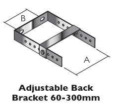
Adjustable Back Bracket 60-300mm Internal and External Application
The adjustable wall bracket is supplied in three parts, a ‘U’ shaped stainless steel B
adjustable section, two bolts for fixing the wall band to the back bracket and a strengthening cross bracket.
- Once the position of the support has been determined, secure the U shaped bracket A to the wall with a method of fixing to ensure adequate attachment and support.
- Determine the amount of extension required and secure the back bracket of the wall band in place onto the adjustable section.
- Fasten the strengthening cross bracket in place using the bolts provided.
- With the back bracket in place, locate the rear portion of the band onto the back bracket, the outer part of the band is then positioned around the chimney section and secured with the nuts and bolts provided.
- The adjustable wall band provides lateral stability only, it is NOT load bearing and is to be positioned at 3 metre centres.
|
Int Ø |
80 |
100 |
130 |
150 |
180 |
200 |
230 |
250 |
300 |
|
Ext Ø |
130 |
150 |
180 |
200 |
230 |
250 |
280 |
300 |
350 |
|
A |
131 |
151 |
181 |
201 |
231 |
251 |
281 |
301 |
351 |
|
B |
72 |
81 |
112 |
132 |
162 |
182 |
214 |
232 |
283 |
|
C |
25 |
25 |
25 |
25 |
25 |
25 |
25 |
25 |
30 |
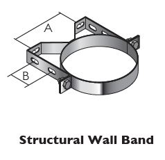
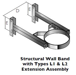
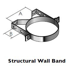 Structural Wall Band
The structural wall band is supplied in two parts, a stainless steel split band which fits tightly around the outside of the chimney and a stainless steel back bracket.The
parts are joined together by means of the nuts and bolts provided. The use of the A
item maintains a fixed distance of 50mm from the outer casing of the chimney to the wall or fixing point. It can be used in combination with the structural wall band
extension components to provide for adjustment to various distances from the wall. B
- Once the position of the support has been determined, secure the back bracket to the wall with a method of fixing to ensure adequate attachment and support.
- The stainless steel split band is then positioned around the chimney section and secured with the nuts and bolts provided to the back bracket.
- The wall bracket provides lateral stability only, it is NOT load bearing and is to be positioned at maximum 4 metre centres.
|
Int Ø |
80 |
100 |
130 |
150 |
180 |
200 |
230 |
250 |
300 |
|
Ext Ø |
130 |
150 |
180 |
200 |
230 |
250 |
280 |
300 |
350 |
|
A |
100 |
120 |
150 |
170 |
200 |
220 |
250 |
270 |
320 |
|
B |
55 |
55 |
55 |
55 |
55 |
55 |
85 |
85 |
85 |
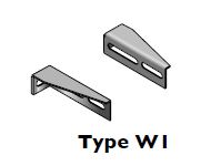
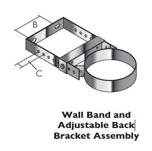
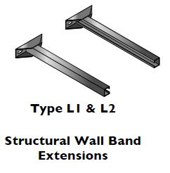 Structural Wall Band Extensions
Available in 3 different sizes.Type W1 gives adjustment of between 55-100mm from the wall. L1 gives adjustment of between 100-250mm from the wall and L2 gives adjustment of between 100-440mm from the wall.
- Once the position of the support has been determined, secure the back bracket to the wall with a method of fixing to ensure adequate attachment and support.
- Fasten the structural wall band to the extension brackets using the nuts and bolts provided.
|
Int Ø |
80 100 130 150 180 200 230 250 300 | ||||||||
|
Ext Ø |
130 150 180 200 230 250 280 300 350 | ||||||||
|
C |
174 194 224 244 274 294 324 344 394 | ||||||||
|
D |
180 200 230 250 280 300 330 350 400 | ||||||||
|
E |
110 |
110 |
110 |
110 |
110 |
110 |
110 |
110 |
110 |

 Base support Plate with Drain
This component is used to support the chimney directly from the floor. It should be fastened securely to the floor using bolts or screws provided by others.
Adjustable Top Plate
The wall support is designed to be used internally or externally to provide either
initial or intermediate support for the vertical chimney. It is used in combination with side plates or with cantilever brackets. The turned down edge at the front of the plates is slotted to allow for the plate to slide along the cantilever brackets and give some positional adjustment. The female socket on the pipe attached to the underside of the plate should be pushed down onto the preceding pipe and the joint secured using the locking band provided. The top plate is then attached to the side plates or the cantilever brackets using the bolts provided through the fixing slots in the top plate (see Fig. 1). The bolts should then be tightened firmly.
|
Int Ø |
80 |
100 |
130 |
150 |
180 |
200 |
230 |
250 |
300 |
|
A |
188 |
208 |
238 |
258 |
278 |
285 |
315 |
335 |
385 |
|
B |
246 |
266 |
296 |
316 |
346 |
366 |
396 |
416 |
471 |
Side Plates/Cantilever Brackets
Once the position of the support has been established in relation to the chimney route, secure the side plates or cantilever brackets to the wall using expansion bolts to ensure adequate attachment and support (see Fig. 2).
Wall Support Side Plates
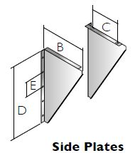
|
Int Ø |
80 100 130 150 180 200 230 250 300 |
|
C |
215 235 265 285 315 335 365 385 440 |
|
D |
145 165 195 215 245 265 295 315 370 |
|
E |
470 470 470 470 470 470 470 470 470 |
|
F |
100 100 100 100 100 100 100 100 100 |
Cantilever Supports
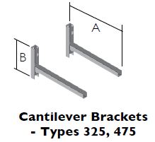
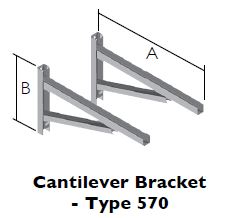
|
Type |
325 |
475 |
570 |
|
Ø Range |
80-200 |
80-300 |
80-300 |
|
A |
325 |
475 |
570 |
|
B |
242 |
242 |
330 |
Cantilever Supports Adjustment
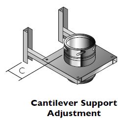
|
Int Ø |
80 |
100 |
130 |
150 |
180 |
200 |
230 |
250 |
300 |
|
C max |
|||||||||
|
Type 325 |
184 |
164 |
134 |
114 |
84 |
64 |
– |
– |
– |
|
Type 475 |
334 |
314 |
284 |
264 |
234 |
214 |
184 |
164 |
114 |
|
Type 570 |
429 |
409 |
379 |
359 |
329 |
309 |
279 |
259 |
209 |
|
C min |
|||||||||
|
Type 325 |
50 |
50 |
50 |
50 |
50 |
50 |
50 |
50 |
50 |
|
Type 475 |
50 |
50 |
50 |
50 |
50 |
50 |
50 |
50 |
50 |
|
Type 570 |
50 |
50 |
50 |
50 |
50 |
50 |
50 |
50 |
50 |
Roof Support
The roof support is supplied as a kit complete with two side plates for fixing to the roof trusses, a band to give lateral support to th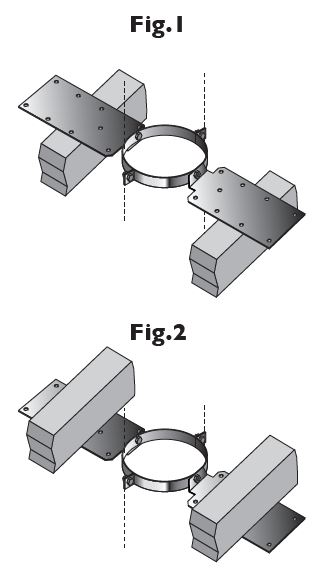 e chimney as it passes through the roof, and 3 self tapping screws, which are secured to the chimney through the band to give a load bearing capacity. When the plates are installed above the roof trusses as in Fig.1 the maximum number of pipes, which may be suspended from the roof support is 6 x 1m pipes. When the plates are attached below the trusses as in Fig.2 the maximum number of pipes, which may be suspended is 4 x 1m pipes.
- The band should be lowered down over the top of the ICS pipe, and positioned so that the the side plates are resting on top of the roof trusses as in Fig.1 or below the roof trusses in the case of Fig. 2.The recommended position is always as per Fig.1 where circumstances allow this solution.
- The band should then be tightened using the nut and bolt provided.
- Using the holes pre-drilled in the roof support band, drill 3mm holes in the outer case of the chimney section (drill bit should be set for a depth no greater than 10mm to avoid any damage to the liner of the chimney)
- Use the self tapping screws provided to secure the clamp band to the outer casing of the chimney section.
Please note: It is the responsibility of the installer to ensure that the joist to which the roof support is being attached is load bearing and capable of withstanding the weight of the system being installed.
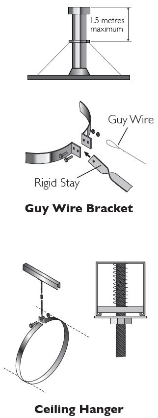 Guy Wire Bracket
This component should be used to secure unsupported chimney sections above roof level. Guy wires or preferably rigid stays (supplied by others) must be fixed to the bracket and secured to suitable anchorage points to ensure that the chimney sections are stable.
A maximum chimney height of 1.5 metres from the last support, or from the roof is permitted. Additional height requirements MUST be supported at 1.5 metre intervals using the guy wire bracket as specified above.
Ceiling Hanger
This accessory is designed to support horizontal runs of the chimney from the roof or ceiling and offers adjustment from 130mm to 1115mm.
- Once the position of the ceiling support has been determined, the section length of uni-rax channel must be securely fixed to the roof or the ceiling using a method of attachment to ensure adequate attachment and support.
- All items are assembled as shown to attach the length of studding to the channel.
- Attach the stud connector to the length of studding and connect the eye bolt to the connector.
- Position the split band around the chimney section and secure to the eye bolt using the nut/bolt provided.
- Maximum support spacing to be no more than 1.5 metres.
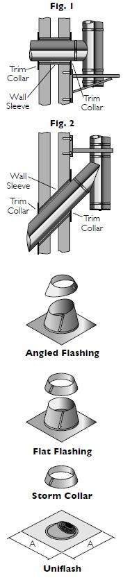 Wall sleeve (90˚ & 135˚ variants)
Wall sleeves must be used to protect the building where the chimney passes through a wall (see Fig. 2 & 3). The 90° version is supplied as a straight length whereas the 135° version is mitred at 45 degrees on one end.The sleeve should be cut down to the correct length on site to fit flush with the wall (see Fig. 1 & 2). The sleeve should be adequately weatherproofed, using a good quality building mastic and rope fibre.
Two Piece Trim Collar (90˚ & 135˚ variants)
Two piece trim collars are fitted around the ICS pipe where it protrudes through both the inside and the outside of the wall (see Fig. 1 & 2). They should be fastened to the wall using an adequate method of fixing. The trim collars should be adequately weatherproofed back to the wall and around the chimney, using a good quality building mastic or equivalent.
Flat Flashing
Manufactured in sheet aluminium for use on flat roofs the base of the flashing should be covered by the roofing felt and then sealed.This component should be sealed with the mastic sealant provided and MUST be used in conjunction with the storm collar supplied.
Storm Collar
The storm collar should be sealed to the outer casing of the flue immediately above the flashing with the mastic sealant provided.
Uniflash
This item, which is manufactured with a malleable base and a silicone cone is used to provide a water tight flashing around the chimney as it passes through a roof pitched between 0-45 degrees.The cone is marked with pipe diameter sizes.
- Cut the cone to suit the correct diameter of chimney.
- Slide the flashing down over the top of the pipe and then form the base to the shape of the roof surface.
- Seal as required.
|
Ext Ø |
80-200 |
150-300 |
250-450 |
|
A |
500 |
685 |
800 |
Terminals
Terminals are supplied complete with a locking band. Once the terminal has been pushed into place, the adjustment bolt on the locking band clip should be tightened to ensure that the terminal is properly secured to the previous pipe.
OUTLET SITING
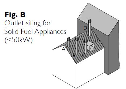
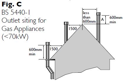
Flue terminations for solid fuel & oil are subject to EN15287-1 2007. Figures A and B illustrate recommendations for the most commonly encountered outlet terminations. Flue terminations for gas in domestic situations are governed by the BS5440-1 2008 Section 4.2. Figure C illustrates recommendations for the most common siting situations encountered. Adjacent taller structures may require increased height. The minimum flue projection through the roof is 600mm to the underside of the terminal.
Outlet siting for Oil Appliances (<45kW)
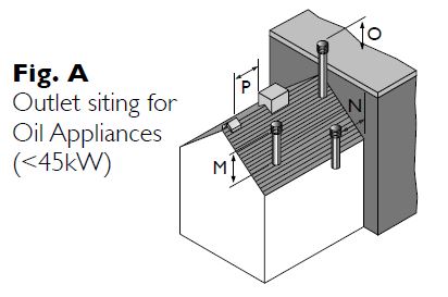
|
Location of outlet |
Pressure Jet Burner |
Vapourising Burner |
|
|
M |
Above the highest point of an intersection with the roof |
600mm |
1000mm |
|
N |
From a structure to the side of the terminal |
750mm |
2300mm |
|
O |
Above a vertical structure which is less than 750mm (pressure jet burner) or 2300mm (vapourising burner) horizontally from the side of the terminal |
600mm |
1000mm |
|
P |
From a ridge terminal to a vertical structure on the roof |
1500mm |
Should not be used |
Outlet siting for Solid Fuel Appliances (<50kW)
|
Point where flue passes through weather surface (Notes I, 2) |
Clearance to flue outlet |
|
|
A |
At or within 600mm of the ridge |
At or within 600mm above the ridge |
|
B |
Elsewhere on the roof (whether pitched or flat) |
At least 2300mm horizontally from the nearest point on the weather surface and: |
|
C |
Below (on a pitched roof) or within 2300mm horizontally to an openable rooflight, dormer window or other opening (Note 3) |
At least I000mm above the top of the opening |
|
D |
Within 2300mm of an adjoining or adjacent building, whether or not beyond the boundary (Note 3) |
At least 600mm above any part of the adjacent building within 2300mm |
- The weather surface is the building external surface, such as its roof, tiles or external walls.
- A flat roof has a pitch less than I0°.
- The clearance for A or B, as appropriate, will also apply.
- A vertical flue fixed to an outside wall should be treated as equivalent to an inside flue emerging at the nearest edge of the roof.
TYPICAL EXTERNAL INSTALLATIONS
Distance between Lateral Supports
|
Int Ø (mm) |
A (m) |
B (m) |
C (m) |
D (m) |
|
80 |
4 |
3 |
15 |
15 |
|
100 |
4 |
3 |
15 |
15 |
|
130 |
4 |
3 |
15 |
15 |
|
150 |
4 |
3 |
15 |
15 |
|
180 |
4 |
3 |
15 |
15 |
|
200 |
4 |
3 |
15 |
15 |
|
230 |
4 |
3 |
15 |
15 |
|
250 |
4 |
3 |
15 |
15 |
|
300 |
4 |
25 |
15 |
15 |
Max Offset Info (in same plane)
LOAD BEARING DATA
Maximum Load Bearing (metres of pipe)
|
Internal Diameter (mm) |
80-130 |
150-180 |
200-300 |
|
Base Drain Section |
22 |
18 |
18 |
|
Adjustable Top Plate + Locking Band |
15 |
15 |
15 |
|
Telescopic Floor Support |
18 |
18 |
18 |
|
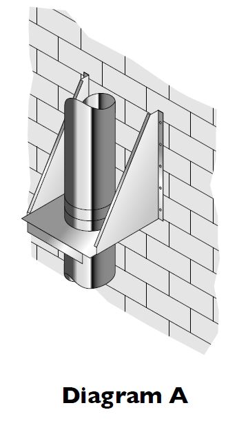
Pair of Side Plates (see Diagram A) |
15 |
15 |
15 |
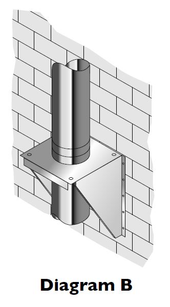
|
Pair of Side Plates (see Diagram B) |
10 |
10 |
10 |
|
Cantilever Support |
22 |
18 |
18 |
|
Extension Support (Anchor Plate) |
1.5 |
1.5 |
1.5 |
|
Ventilated Support Plate (All types) |
12 |
12 |
9 |
|
Support Plate |
12 |
12 |
9 |
|
Ceiling Hanger |
1.5 |
1.5 |
1.5 |
|
Wall Band 50/60mm |
3 |
3 |
3 |
|
Adjustable Wall Band 60-300mm |
3 |
3 |
3 |
|
Structural Wall Band |
4 |
4 |
4 |
|
Extension for Structural Wall Band |
4 |
4 |
4 |
|
Guy Wire Bracket |
1.5 |
1.5 |
1.5 |
|
Roof Support above truss (see Fig. 1 p.19) |
6 |
6 |
6 |
|
Roof Support – below truss (see Fig. 2 p.19) |
4 |
4 |
4 |
|
90° Tee + Locking Band |
22 |
18 |
18 |
|
93° Tee + Locking Band |
22 |
18 |
18 |
|
135° Tee + Locking Band |
15 |
10 |
10 |
|
Inspection Tee (Round) |
22 |
18 |
18 |
|
Inspection Tee (Rectangular) |
22 |
18 |
18 |
COMPONENT WEIGHTS
Approximate Weights of Finished Goods (Kg)
|
Internal Diameter Length(mm) |
1000 |
750 |
500 |
250 |
195 |
|
80mm |
4.32 |
– |
2.13 |
1.09 |
0.85 |
|
100mm |
5.14 |
– |
2.53 |
1.29 |
1.01 |
|
130mm |
6.35 |
4.74 |
3.14 |
1.60 |
1.24 |
|
150mm |
7.18 |
5.36 |
3.54 |
1.86 |
1.41 |
|
180mm |
8.40 |
– |
4.14 |
2.11 |
1.65 |
|
200mm |
9.22 |
– |
4.55 |
2.31 |
1.80 |
|
230mm |
10.44 |
– |
5.13 |
2.62 |
2.03 |
|
250mm |
11.24 |
– |
5.53 |
2.81 |
2.19 |
|
300mm |
12.08 |
– |
5.97 |
2.92 |
2.29 |
AFTER INSTALLATION
Testing and Commissioning prior to first use
This is carried out using a flue flow test as described in BS EN 15287 Parts 1 & 2, with reference to the appropriate appliance type.
Appliance Operation
If the appliance is slumbered overnight or for longer periods then it is advisable to run the appliance at controlled high fire condition for a period of at least 30 minutes. Prolonged slumbering of the appliance is a contributing factor to a system chimney failure. It is important to maintain sufficiently high flue gas temperatures in order to avoid condensate and acid corrosion problems, and to ensure complete combustion of the fuel.
Multi-Fuel Applications
Multi-Fuel refers to an appliance which may be used to burn either seasoned wood, or approved solid fuels.These fuels should not be mixed, as this increases the risk of deposits being built up in the liner.
Maintenance
Each chimney must be designed to allow for easy inspection; sweeping should be carried out by competent persons. On solid fuel applications a list of HETAS registered sweeps can be found at www.hetas.co.uk. Chimney flue cleaning and inspection require the use of appropriate tooling – under no circumstances should chemical cleaners or mild steel tools be used to sweep stainless steel chimneys. Mechanical sweeping methods such as Rodtech, Rodstation and Gardus, which have been tested and approved by Schiedel Chimney Systems may be used. Cleaning/inspection of any chimney system should be carried out at least once a year, along with maintenance of the appliance, but it is recommended that chimneys serving solid fuel appliances be swept at least twice a year, at the end of the heating season to remove any deposits, which may have built up during the season, and prior to the start of the next heating season to ensure that the the flue way is clear of any blockages such as birds nests etc.
We would advise that monthly checks are carried out to ensure that there is no build up of any deposits in the flue way of the connecting flue pipe or system chimney.
Fuel Storage and Usage
Where solid fuels are being used, correct storage is critical and fuels must be kept dry. Wood must be seasoned prior to use, with a maximum moisture content of 20%. Only approved fuels should be used. Refer to HETAS list for details on www.hetas.co.uk. The fuel used must be suitable for the appliance – please refer to manufacturer’s instructions.
NOTICE PLATE
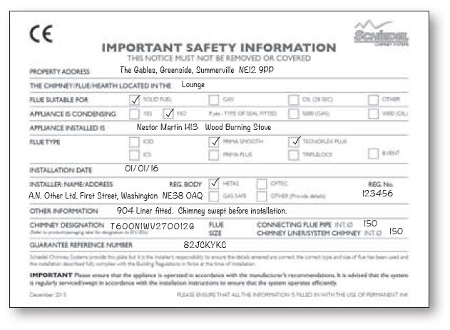
The Notice plate should be marked up in indelible ink and securely fixed in an unobtrusive but obvious position within the building such a
PRODUCT GUARANTEE
Under normal operating conditions and providing the system is installed correctly, it should last the lifetime of the appliance, which normally is 10 years. ICS carries a 10 year conditional guarantee.The conditions are that the system is:-
- Correctly sized and installed in accordance with the manufacturer’s instructions, current Building Regulations and relevant British and European standards.
- Maintained correctly by a qualified and competent person and maintenance records kept updated for both appliance and system chimney.
- Used in combination with an appliance burning only approved fuels in accordance with Schiedel Chimney Systems and the appliance manufacturer’s instructions.
- The product registration form must have been filled in by an appropriately qualified installer (see p.3 for details), and returned to Schiedel Chimney Systems Ltd.
For recommended fuels listings, please refer to the HETAS Guide www.hetas.co.uk
In the event of a fault developing in the product due to defective materials or faulty manufacture Schiedel Chimney Systems undertake to replace the product only.
Schiedel Chimney Systems cannot accept liability nor take any responsibility for the installation, building or redecorating costs or any other consequential losses arising.
If any complaint is found to be a result of faulty installation, non-compliance with or abuse contrary to these conditions, the cost of site investigation is chargeable.
Product Registration
We have upgraded our guarantee registration system. Please click here to register
If for any reason you are unable to register online, please contact our offices and a paper version will mailed to you.
Please Note: An incomplete registration could make your warranty void.