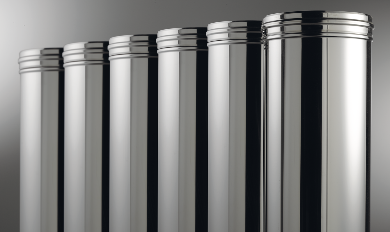
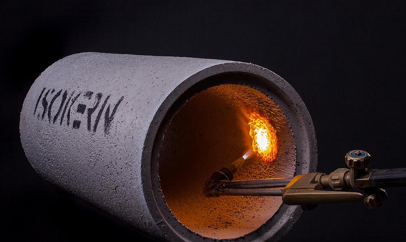
<\/a>Typical installation<\/h3>\n[\/vc_column_text][vc_row_inner disable_element=”yes”][vc_column_inner width=”1\/2″][vc_column_text css=”.vc_custom_1670320856006{margin-bottom: 0px !important;}”]\nInstallation inside the house<\/h4>\n
UK Plus is mounted directly on top of the appliance and consists only of vertical sections of the flue.<\/p>\n
If the length of the flue exceeds the load bearing capacity of the appliance, weight can be distributed by installing a support plate in the ceiling structure.<\/p>\n
In national regulations of some EU countries (including UK & ROI) flues penetrating living areas must be installed in enclosures to meet building regulation.[\/vc_column_text][\/vc_column_inner][vc_column_inner width=”1\/2″][mk_image src=”https:\/\/www.schiedel.com\/uk\/wp-content\/uploads\/sites\/12\/2022\/12\/installation-inside-the-house.jpg” image_size=”full”][\/vc_column_inner][\/vc_row_inner][vc_row_inner][vc_column_inner width=”1\/2″][vc_column_text css=”.vc_custom_1670320866055{margin-bottom: 0px !important;}”]\n
Installation on the outside wall<\/h4>\n
The connecting flue pipe runs at an angle of 3\u00b0 through the outside wall with transition into the vertical run through an 87\u00b0 bend.<\/p>\n
The vertical section of the flue is supported with a top plate installed immediately above the bend and additionally secured with cantilever brackets.<\/p>\n
An offset can be included into vertical run to avoid penetration through the roof.[\/vc_column_text][\/vc_column_inner][vc_column_inner width=”1\/2″][mk_image src=”https:\/\/www.schiedel.com\/uk\/wp-content\/uploads\/sites\/12\/2022\/12\/installation-on-the-outside-wall.jpg” image_size=”full”][\/vc_column_inner][\/vc_row_inner][vc_row_inner][vc_column_inner width=”1\/2″][vc_column_text css=”.vc_custom_1670320873166{margin-bottom: 0px !important;}”]\n
Installation through the outside wall<\/h4>\n
The connecting flue pipe runs at an angle of 3\u00b0 through the outside wall and terminates with a horizontal terminal.<\/p>\n
The design of the terminal prevents recirculation of flue gases into combustion air.<\/p>\n
The national regulations should be checked prior to such installation as some countries limit the max. allowed heat output.[\/vc_column_text][\/vc_column_inner][vc_column_inner width=”1\/2″][mk_image src=”https:\/\/www.schiedel.com\/uk\/wp-content\/uploads\/sites\/12\/2022\/12\/installation-through-the-outside-wall.jpg” image_size=”full”][\/vc_column_inner][\/vc_row_inner][\/vc_column][\/vc_row][vc_row][vc_column][vc_tta_accordion active_section=”0″ no_fill=”true”][vc_tta_section i_icon_fontawesome=”far fa-object-group” add_icon=”true” title=”Design guide” tab_id=”1670321014837-181f348f-89e2″][vc_column_text css=”.vc_custom_1670323267660{margin-bottom: 0px !important;}”]\n
Mandatory requirements<\/h4>\n
The system must be installed according to European Norms, national building regulations and instructions of the manufacturer as indicated in the documentation. Apart from the general instructions there are specific instructions in connection with the type of connected gas appliance. Always refer to installation instructions of the boiler manufacturer for details. Special attention should be drawn to max. permitted pipe length of the flue system (can be found in appliance installation manual). In some cases a special appliance adaptor should be used to connect the appliance with UK Plus flue system.<\/p>\n
The connection to the appliance may be carried out only by a competent person. Connection to an appliance that is connected to the fuel supply must be carried out by a Gas Safe (Gas) or OFTEC (Oil) registered installer.<\/p>\n
Flue diameter<\/h4>\n
The chimney size should be as recommended by the appliance manufacturer. The operational requirements of the appliance and the configuration of the flue must satisfy the flue sizing requirements of EN13384-1.<\/p>\n
Flue route<\/h4>\n
The flue should remain as straight as possible through its entire length to assist flow. Bear in mind that each tight bend reduces max. permitted pipe length.<\/p>\n
Distance to combustibles<\/h4>\n
In accordance with building regulations, it is essential that the correct distance to combustible material is maintained. UK Plus is suitable for use with low temperature or condensing gas and oil appliances with flue gas temperatures < 200\u00b0C. Where used as a System Chimney at low temperature, the system may be installed with 0mm distance to combustibles.<\/p>\n
Where the system is being used in the horizontal at low temperature , <200\u00b0C, then a distance to combustibles of 30mm is required.
\nWhere used on a high temperature application where flue gases could be up to 600\u00b0C, then a distance to combustibles of 50mm is required. In this application the chimney must be fully ventilated.<\/p>\n
Enclosure\/Shafts<\/h4>\n
With the exception of the room containing the appliance, where the chimney passes through any part of the building, where there is a risk of accidental human contact, i.e. a bedroom etc., or where there is a risk of contact with combustible materials, the chimney must be enclosed in an appropriate way to meet Building regulations. The minimum distance to any combustible material, including loft insulation, must be respected.<\/p>\n
Inspection<\/h4>\n
According to national regulation, provisions should be made to enable easy access for inspection and cleaning. Respective national building code and requirements of appropriate standards should be observed. We recommend to consult competent chimney sweeper on the arrangement of the inspection openings.<\/p>\n
Provision for condensate disposal (subject to appliance manufacturer recommendations)<\/h4>\n
Condensing appliances need provision for drainage. Choose appropriate flue drainage components, normally fitted at the base of the stack and close to the appliance outlet. A 3\u00b0 slope (5 cm\/m) from vertical run towards the appliance must be maintained, using the appropriate 87\u00b0 bend and 87\u00b0 tee. On longer horizontal runs there might be additional supports required to support the flue in order to maintain the required slope.<\/p>\n
Appliance\/Chimney Connection<\/h4>\n
Connection to the appliance should be done by using appropriate appliance connector.<\/p>\n
Requirements on location of flue\/gas system termination.<\/h4>\n
Flue termination for gas appliances are subject to EN 15287-1. Annex M gives recommendations for the most common siting situations encountered. Adjacent taller structures and roof windows may require increased height. Please refer also to requirements on air\/flue pipe outlet specified in installation instructions of the connected appliance.<\/p>\n
Lightning protection<\/h4>\n
Stainless steel flue gas system can be damaged by a lightning strike. If a building has a lightning conductor circuit make sure that flue gas system is linked to it.<\/p>\n
Support Components<\/h4>\n
The weight of a chimney system requires independent support. Minimal weight should be borne by the appliance. The weight of the chimney can be supported from floor level by using a base support plate, or floor support; from the wall by using wall support top plates together with side plates or cantilever brackets; or from first floor level by using a support plate fixed to the floor\/ceiling joists.<\/p>\n
Wall brackets are non load bearing and provide lateral support only. Refer to the load bearing tables for full details of maximum loadings.<\/p>\n
Free standing height above the roof<\/h4>\n
Where the flue is freestanding above the roof and its height exceeds 1.5 m above the last support or above the roof, a guy wire bracket must be used and every 1.5 m thereafter in conjunction with guy wires or rigid stays (provided by others). Alternatively a height of up to 3 m can be achieved unsupported using extended locking bands at the joint immediately below the last support and on every joint above it.<\/p>\n
CE data plate<\/h4>\n
After installation a chimney plate must be applied. This is the responsibility of the installer.[\/vc_column_text][vc_column_text css=”.vc_custom_1670323256908{margin-bottom: 0px !important;}”][\/vc_column_text][vc_row_inner css=”.vc_custom_1670322952230{margin-left: 0px !important;border-left-width: 0px !important;padding-left: 0px !important;}”][vc_column_inner width=”2\/3″ css=”.vc_custom_1670322995296{margin-left: 0px !important;border-left-width: 0px !important;padding-left: 0px !important;}”][vc_column_text css=”.vc_custom_1670323045745{margin-bottom: 0px !important;}”]\n
Load bearing information<\/h4>\n