The video shows a guide on how to install a DM system.
FOUNDATIONS
Construction begins by providing a suitable foundation and constructional hearth in accordance with Building Regulations and site requirements.
OPEN FIRE OPTION
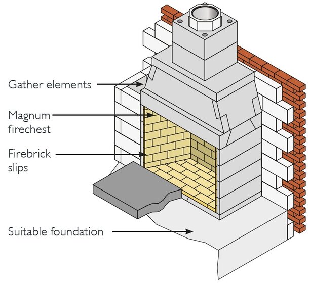
Bed the base plate of the firechest onto a suitable foundation/constructional hearth in accordance with Building Regulations and at the level required on site using Isokern lip glue.
Install the firechest using lip glue making sure all elements are level. 100mm of brick/blockwork must be built around the sides and back of the firechest to comply with Building Regulations. The inside of the firechest must be finished with a suitable fireback or firebrick slips.
Install the gather using lip glue making sure all the elements are level. The front face of the gather can be finished with plasterboard, rendered or clad in masonry. Lintels may be required above the gather to help carry the brick or blockwork. The maximum loading capacity of the ISOKERN firechest and gather is 2500kg.
STOVE IN RECESS OPTION
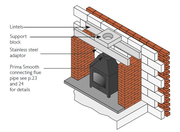
Pre-stressed lintels or a suitable cast-in-situ concrete slab must be provided above the stove recess, please make sure they are strong enough to carry the load (see appropriate Isokern DM drawing for aperture size). It is recommended to have a minimum of 600mm of stove flue pipe before connecting to the support block.
The support block is bedded onto the lintels using a weak mix mortar. A stainless steel adaptor is used to create a positive connection from the support block to the stove flue pipe (fibre rope should be used to create a seal).
FREE STANDING STOVE OPTION
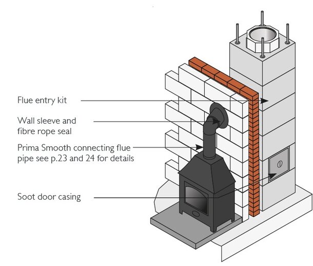
A soot door casing and access flue block must be used below the flue pipe entry. The DM 45˚ access kit is then used for the connecting flue pipe. A suitable wall sleeve must be used to seal the cavity wall. Any combustible insulation within the wall must then be kept away from the single wall connecting flue pipe by at least 1.5 x its diameter. Fibre rope is used to seal between the flue pipe and wall sleeve, a suitable trim collar can be used to finish the inner wall surface.
CHIMNEY CONSTRUCTION
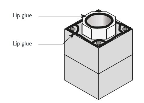
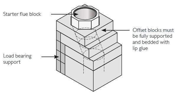
Bed the first outer casing using lip glue making sure the rebate (raised lip) is uppermost. The starter flue block is then put inside the casing bedded with lip glue. The socket on the starter flue block must be uppermost and the air gap between the starter flue and the casing should be kept clear. The finished lip glue joints should be 2-3mm thick, a special bag is provided for ease of application and the lip glue should be applied in 12-15 mm beads.
Offset blocks if required must be glued together with lip glue and be fully supported. Please note a chimney should be built straight wherever possible. A starter flue block will be required above the offset blocks to stagger the joints between the outer casing and inner flue blocks.
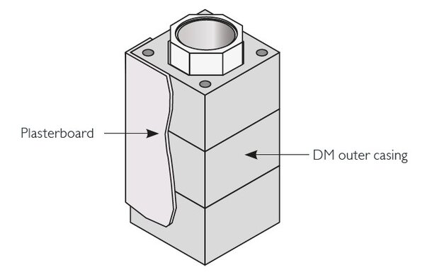
Casings and flue blocks are added using lip glue for all joints. Ensure the air gap between the inner flue and outer casing remains clear. The outer surface of the casings to be finished with plasterboard on dabs or plaster. The side that faces the wall does not need an external finish.
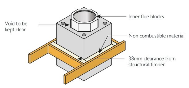
On a rendered stack with a top ring fitted (see p.12 for example), where a straight chimney passes through a floor or roof, zero mm distance to combustibles can be applied. A sliding joint is made using mineral wool or similar non-combustible material. In all other cases, 38mm clearance must be maintained between the outer face of the chimney and any structural timber or combustible material. Floor boards, skirting boards, dado rails and other non-structural components may, however, be in contact with the chimney.
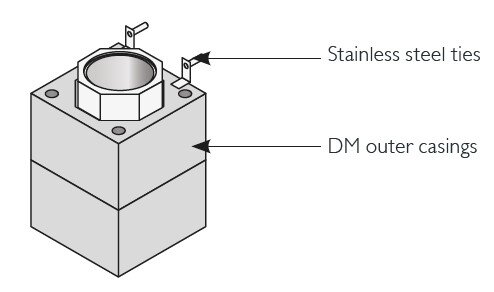
External chimneys must be tied to the structure at maximum intervals of 1.5m and at the point where it departs from the roof using 2 x suitable stainless steel wall ties. These are fitted into the outer casing joints. They are not always required for internal chimneys. Please consult the Isokern technical office.
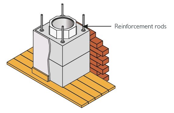
High tensile steel reinforcement rods will be required for all chimneys with a height that exceeds 1.4m above the roof line, 1.1m if the wind speed exceeds 44ms. These rods are available from Isokern and must be grouted (1:3 cement/sand) into the holes provided in the outer casings. You must start the rods at least the same height below the roof as what’s above, please check with our technical department.
RENDERED STACK OPTION
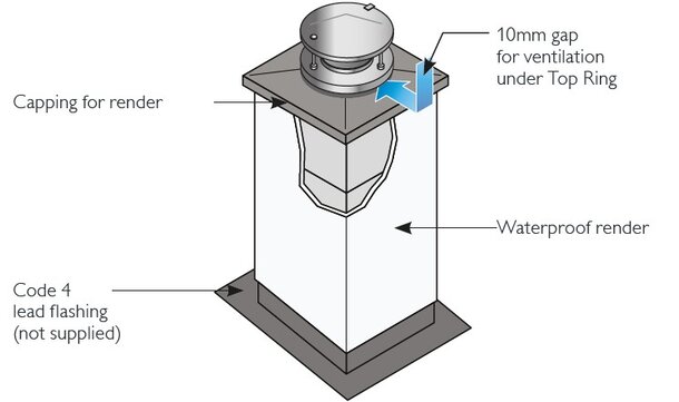
Code 4 lead flashing to be fitted at roof level as per Building Regulations. We recommend that you scorch a 5-10mm deep channel into the outer surface of the casings and fold in the top edge of the flashing.
Finish the outer surface of the casings above the roof with 2 part waterproof render. The recommended mix is 1:2:5-6 cement:lime:sand for the undercoats. 1:2:8-9 cement:lime:sand for the final coat. The number of coats required will depend upon the degree of exposure, generally a two coat mix is acceptable. The mix may vary due to climate conditions, the thickness of any one coat should not exceed 15mm, and each subsequent coat should be reduced by approximately 3mm.
Isokern concrete capping for render to be lip glued onto the last casing.
BRICK STACK OPTION
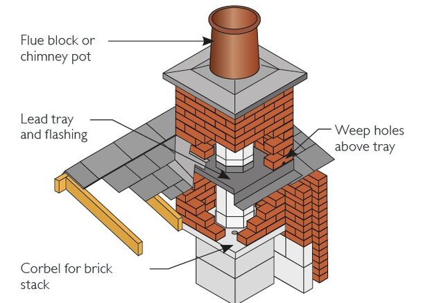
To take brick or stonework externally a corbel is fitted just below the roof. Use trusses and trimmers to brace the cladding as it passes through the roof.
Code 4 lead tray with 50mm upstands and stepped flashing to be fitted in accordance with Building Regulations. A 50mm upstand should be fitted tight to the outside of the flue block and where possible turned in by approx 10mm. Lead trays should be coated with bituminous paint where it is in contact with mortar. The D.P.C. tray should be fitted at least 150mm above the lowest point of intersection with the roof. Weep holes should be provided at the front of the stack above the tray for water drainage.
Casings can be deleted above the corbel if stack height is less than 1.4m above the roof.
TERMINATION
Raincap - Ventilated Option - (Installation with 0 distance to combustibles for straight rendered chimneys only). Take the last flue block up through the capping, do not fill the gap between the flue block and capping. Push fit the aluminium top ring onto the flue block and make sure there is a 10mm air gap between the outer edge of the ring and the capping. The flue block may need cutting to suit.
Chimney Pot Option - This option always requires a 38mm distance to combustibles from the outside of the block. Fit a chimney pot at least 75mm down into the capping and flaunch with 1:3 cement and sharp sand to seal around. This option is not possible if 0 distance to combustibles is required.
After installation is complete tests and checks should be carried out in accordance with document J of the Building Regulations. A chimney notice plate must be completed and permanently fixed in the dwelling, ideally near the electrical consumer unit. The checklist and notice plate are available from Schiedel Isokern.
USE AND MAINTENANCE
The chimney should be left for at least 72 hours before use, then start only with small fires for the first week and gently increase thereafter.
The chimney should be swept at least twice a year, once before the heating season and once after the heating season. You may need to sweep during the heating season depending upon use. The brush should be a medium density polypropylene bristle type and should be the same diameter as the flue. Steel brushes must not be used to sweep the Isokern pumice flues. Always follow the appliance manufacturer’s operating instructions. Always burn approved fuels or dry seasoned wood. Avoid burning unseasoned wood and slow burning of solid fuels as this can produce excessive soot and condensation which in turn cause soot fires and damage. If correctly installed, operated and maintained these systems could last the life of the dwelling.
Connection to an appliance, which is not connected to the fuel supply, may be carried out by a competent person. However, connection to an appliance, which is connected to the fuel supply, must be carried out by a GAS SAFE (gas) or OFTEC (oil) registered installer.
Schiedel Chimney Systems Ltd. recommends the use of HETAS registered installers for solid fuel applications.
This installation assistant is to be used as a visual aide only, by qualified installers, in conjunction with the detailed component installation instructions. For full design and installation details, the key referral documents are as follows:-
Appliance Installation Instructions and related standards. Other standards covering specific applications will also be relevant and should be adhered to.
Planning permission may be required and reference should be made to the local Building Control Department.
Ensure all chimney components are available and check them to ensure there has been no damage.
Do not use damaged components. Build the chimney up to follow the previously designed route, which should be as straight as possible.